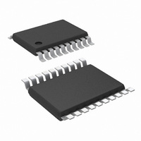
LM3102MH/NOPB National Semiconductor, LM3102MH/NOPB Datasheet - Page 3

LM3102MH/NOPB
Manufacturer Part Number
LM3102MH/NOPB
Description
IC BUCK SYNC ADJ 2.5A 20TSSOP
Manufacturer
National Semiconductor
Series
PowerWise®, SIMPLE SWITCHER®r
Type
Step-Down (Buck)r
Specifications of LM3102MH/NOPB
Internal Switch(s)
Yes
Synchronous Rectifier
Yes
Number Of Outputs
1
Voltage - Output
0.8 ~ 7 V
Current - Output
2.5A
Frequency - Switching
1MHz
Voltage - Input
4.5 ~ 42 V
Operating Temperature
-40°C ~ 125°C
Mounting Type
Surface Mount
Package / Case
20-TSSOP Exposed Pad, 20-eTSSOP, 20-HTSSOP
Current, Output
2.5 A
Current, Supply
0.7 mA
Frequency, Oscillator
1 MHz
Package Type
eTSSOP
Regulator Type
Buck (Step-Down)
Resistance, Thermal, Junction To Case
6.5 °C/W
Temperature, Operating, Range
-40 to +125 °C
Voltage, Dropout
350 mV
Voltage, Input
4.5 to 42 V
Voltage, Output
0.8 to 38 V
Dc To Dc Converter Type
Step Down
Pin Count
20
Input Voltage
42V
Output Voltage
0.8 to 7V
Switching Freq
1000KHz
Output Current
2.5A
Efficiency
92%
Output Type
Adjustable
Switching Regulator
Yes
Mounting
Surface Mount
Input Voltage (min)
4.5V
Operating Temp Range
-40C to 125C
Operating Temperature Classification
Automotive
For Use With
LM3102EVAL - BOARD EVALUATION LM3102
Lead Free Status / RoHS Status
Lead free / RoHS Compliant
Power - Output
-
Lead Free Status / Rohs Status
RoHS Compliant part
Electrostatic Device
Other names
*LM3102MH
*LM3102MH/NOPB
LM3102MH
*LM3102MH/NOPB
LM3102MH
Pin Descriptions
1,9,10,12,19,
17, 18
2, 3
4, 5
Pin
EP
20
11
13
14
15
16
6
7
8
B3, C2, C3,
A1, B1, C1,
A2, A3, B2,
D2, D3, D4
E3, E4, F1,
F2, F3, G3
A4, B4
E1, E2
Ball
C4
G2
G1
G4
D1
F4
AGND
PGND
Name
GND
RON
VCC
BST
N/C
VIN
SW
EN
SS
FB
EP
Description
No Connection
Switching Node
Input supply voltage
Connection for bootstrap
capacitor
Analog Ground
Soft-start
Ground
Feedback
Enable pin
On-time Control
Start-up regulator Output
Power Ground
Exposed Pad
3
Application Information
These pins must be left unconnected.
Internally connected to the source of the main
MOSFET and the drain of the Synchronous
MOSFET. Connect to the inductor.
Supply pin to the device. Nominal input range is
4.5V to 42V.
Connect a 33 nF capacitor from the SW pin to
this pin. An internal diode charges the capacitor
during the main MOSFET off-time.
Ground for all internal circuitry other than the
PGND pin.
An 8 µA internal current source charges an
external capacitor to provide the soft- start
function.
Must be connected to the AGND pin for normal
operation. The GND and AGND pins are not
internally connected.
Internally connected to the regulation and over-
voltage comparators. The regulation setting is
0.8V at this pin. Connect to feedback resistors.
Connect a voltage higher than 1.26V to enable
the regulator.
An external resistor from the VIN pin to this pin
sets the main MOSFET on-time.
Nominally regulated to 6V. Connect a capacitor
of not less than 680 nF between the VCC and
AGND pins for stable operation.
Synchronous MOSFET source connection. Tie
to a ground plane.
Thermal connection pad. Connect to the ground
plane.
www.national.com


