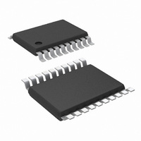
LM5116MH/NOPB National Semiconductor, LM5116MH/NOPB Datasheet - Page 21

LM5116MH/NOPB
Manufacturer Part Number
LM5116MH/NOPB
Description
IC CTRLR SYNCH BUCK 20-TSSOP
Manufacturer
National Semiconductor
Series
PowerWise®r
Type
Step-Down (Buck)r
Datasheet
1.LM5116MHNOPB.pdf
(26 pages)
Specifications of LM5116MH/NOPB
Internal Switch(s)
No
Synchronous Rectifier
Yes
Number Of Outputs
1
Voltage - Output
1.22 ~ 80 V
Current - Output
20A
Frequency - Switching
50kHz ~ 1MHz
Voltage - Input
6 ~ 100 V
Operating Temperature
-40°C ~ 125°C
Mounting Type
Surface Mount
Package / Case
20-TSSOP Exposed Pad, 20-eTSSOP, 20-HTSSOP
Dc To Dc Converter Type
Synchronous Buck Controller
Pin Count
20
Input Voltage
6 to 100V
Output Voltage
1.215 to 80V
Output Current
3.5A
Package Type
TSSOP EP
Mounting
Surface Mount
Operating Temperature Classification
Automotive
Operating Temperature (min)
-40C
Operating Temperature (max)
125C
For Use With
LM5116-12EVAL - BOARD EVALUATION FOR LM5116-12LM5116EVAL - BOARD EVALUATION LM5116
Lead Free Status / RoHS Status
Lead free / RoHS Compliant
Power - Output
-
Lead Free Status / Rohs Status
Compliant
Other names
LM5116MH
The regulator has an exposed thermal pad to aid power dis-
sipation. Selecting MOSFETs with exposed pads will aid the
power dissipation of these devices. Careful attention to R
(ON)
a MOSFET with low gate capacitance will result in lower
switching losses.
Comprehensive Equations
CURRENT SENSE RESISTOR AND RAMP CAPACITOR
T = 1 / f
current at current limit.
General Method for V
General Method for 5V < V
Best Performance Method:
This minimizes the current limit deviation due to changes in
line voltage, while maintaining near optimal slope compen-
sation.
Calculate optimal slope current, I
example, at V
at high temperature should be observed. Also, at 250 kHz,
SW
, g
m
= 5µA/V, A = 10V/V. I
OUT
= 7.5V, I
OUT
< 5V:
OS
OUT
= 25µA.
< 7.5V:
OS
OUT
= (V
is the maximum output
OUT
/ 3) x 10µA/V. For
DS
21
Calculate V
For V
For V
made with a simple charge pump from the LO gate output.
Install a resistor from the RAMP pin to the negative VCC.
If a large variation is expected in VCC, say for V
Zener regulator may be added to supply a constant voltage
for R
RAMP
OUT
OUT
FIGURE 15. R
FIGURE 14. R
> 7.5V, install a resistor from the RAMP pin to VCC.
.
< 7.5V, a negative VCC is required. This can be
RAMP
at the nominal input voltage.
RAMP
RAMP
to -VCC for V
to VCC for V
30007573
30007575
OUT
OUT
> 7.5V
< 7.5V
www.national.com
IN
< 11V, a


