LM2586T-3.3/NOPB National Semiconductor, LM2586T-3.3/NOPB Datasheet - Page 24
LM2586T-3.3/NOPB
Manufacturer Part Number
LM2586T-3.3/NOPB
Description
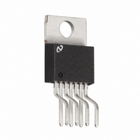
IC REG SIMPLE SWITCHER TO220-7
Manufacturer
National Semiconductor
Series
SIMPLE SWITCHER®r
Type
Step-Up (Boost), Flyback, Forward Converterr
Datasheet
1.LM2586S-ADJNOPB.pdf
(30 pages)
Specifications of LM2586T-3.3/NOPB
Internal Switch(s)
Yes
Synchronous Rectifier
No
Number Of Outputs
1
Voltage - Output
3.3V
Current - Output
3A
Frequency - Switching
100kHz ~ 200kHz
Voltage - Input
4 ~ 40 V
Operating Temperature
-40°C ~ 125°C
Mounting Type
Through Hole
Package / Case
TO-220-7 (Bent and Staggered Leads)
For Use With
551011367-051 - BOARD WEBENCH BUILD IT LM2586/88
Lead Free Status / RoHS Status
Lead free / RoHS Compliant
Power - Output
-
Other names
*LM2586T-3.3
*LM2586T-3.3/NOPB
LM2586T-3.3
*LM2586T-3.3/NOPB
LM2586T-3.3


www.national.com
Typical Boost Regulator Applications
Note 24: The LM2586 will require a heat sink in these applications. The size
of the heat sink will depend on the maximum ambient temperature. To
calculate the thermal resistance of the IC and the size of the heat sink
needed, see the “Heat Sink/Thermal Considerations” section in the Applica-
tion Hints.
SHUTDOWN CONTROL
A feature of the LM2586 is its ability to be shut down using
the ON /OFF pin (pin 1). This feature conserves input power
by turning off the device when it is not in use. For proper
operation, an isolation diode is required (as shown in Figure
38).
The device will shut down when 3V or greater is applied on
the ON /OFF pin, sourcing current into pin 1. In shut down
mode, the device will draw typically 56 µA of supply current
(16 µA to V
device back on, leave pin 1 floating, using an (isolation)
diode, as shown in Figure 38 (for normal operation, do not
source or sink current to or from this pin — see the next
section).
IN
and 40 µA to the ON /OFF pin). To turn the
FIGURE 37. +24V to +48V Boost Regulator
FIGURE 38. Shutdown Operation
24
(Continued)
Application Hints
LM2586 SPECIAL FEATURES
FREQUENCY ADJUSTMENT
The switching frequency of the LM2586 can be adjusted with
the use of an external resistor. This feature allows the user to
optimize the size of the magnetics and the output capaci-
tor(s) by tailoring the operating frequency. A resistor con-
nected from pin 1 (the Freq. Adj. pin) to ground will set the
switching frequency from 100 kHz to 200 kHz (maximum).
As shown in Figure 38, the pin can be used to adjust the
frequency while still providing the shut down function. A
curve in the Performance Characteristics Section graphs the
resistor value to the corresponding switching frequency. The
table in Figure 39 shows resistor values corresponding to
commonly used frequencies.
However, changing the LM2586’s operating frequency from
its nominal value of 100 kHz will change the magnetics
selection and compensation component values.
01251658
01251657
Related parts for LM2586T-3.3/NOPB
Image
Part Number
Description
Manufacturer
Datasheet
Request
R

Part Number:
Description:
Power Supply IC
Manufacturer:
National Semiconductor
Datasheet:

Part Number:
Description:
DC/DC Converter IC
Manufacturer:
National Semiconductor
Datasheet:

Part Number:
Description:
Manufacturer:
National Semiconductor
Datasheet:

Part Number:
Description:
IC REG SIMPLE SWITCHER TO-220-7
Manufacturer:
National Semiconductor
Datasheet:
Part Number:
Description:
IC REG SIMPLE SWITCHER TO-220-7
Manufacturer:
National Semiconductor
Datasheet:
Part Number:
Description:
IC MULTI CONFIG SYNC 12V TO220-7
Manufacturer:
National Semiconductor
Datasheet:
Part Number:
Description:
National Semiconductor [8-Bit D/A Converter]
Manufacturer:
National Semiconductor
Datasheet:
Part Number:
Description:
National Semiconductor [Media Coprocessor]
Manufacturer:
National Semiconductor
Datasheet:
Part Number:
Description:
Digitally Controlled Tone and Volume Circuit with Stereo Audio Power Amplifier, Microphone Preamp Stage and National 3D Sound
Manufacturer:
National Semiconductor
Datasheet:
Part Number:
Description:
Digitally Controlled Tone and Volume Circuit with Stereo Audio Power Amplifier, Microphone Preamp Stage and National 3D Sound
Manufacturer:
National Semiconductor
Datasheet:
Part Number:
Description:
AC97 Rev 2 Codec with Sample Rate Conversion and National 3D Sound
Manufacturer:
National Semiconductor
Part Number:
Description:
Manufacturer:
National Semiconductor
Datasheet:
Part Number:
Description:
Manufacturer:
National Semiconductor
Datasheet: