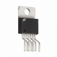
LM2677T-5.0/NOPB National Semiconductor, LM2677T-5.0/NOPB Datasheet - Page 11

LM2677T-5.0/NOPB
Manufacturer Part Number
LM2677T-5.0/NOPB
Description
IC REG SIMPLE SWITCHER TO-220-7
Manufacturer
National Semiconductor
Series
SIMPLE SWITCHER®r
Type
Step-Down (Buck)r
Datasheet
1.LM2677SD-ADJNOPB.pdf
(26 pages)
Specifications of LM2677T-5.0/NOPB
Internal Switch(s)
Yes
Synchronous Rectifier
No
Number Of Outputs
1
Voltage - Output
5V
Current - Output
5A
Frequency - Switching
260kHz
Voltage - Input
8 ~ 40 V
Operating Temperature
-40°C ~ 125°C
Mounting Type
Through Hole
Package / Case
TO-220-7 (Bent and Staggered Leads)
Primary Input Voltage
12V
No. Of Outputs
1
Output Voltage
5V
Output Current
5A
No. Of Pins
7
Operating Temperature Range
-40°C To +125°C
Msl
MSL 1 - Unlimited
Supply Voltage Range
8V To 40V
Rohs Compliant
Yes
Filter Terminals
Through Hole
Lead Free Status / RoHS Status
Lead free / RoHS Compliant
Power - Output
-
Other names
*LM2677T-5.0
*LM2677T-5.0/NOPB
LM2677T-5.0
*LM2677T-5.0/NOPB
LM2677T-5.0
DESIGN CONSIDERATIONS
Power supply design using the LM2677 is greatly simplified
by using recommended external components. A wide range
of inductors, capacitors and Schottky diodes from several
manufacturers have been evaluated for use in designs that
cover the full range of capabilities (input voltage, output volt-
age and load current) of the LM2677. A simple design proce-
dure using nomographs and component tables provided in
this data sheet leads to a working design with very little effort.
Alternatively, the design software, LM267X Made Simple
(version 6.0), can also be used to provide instant component
selection, circuit performance calculations for evaluation, a
bill of materials component list and a circuit schematic.
INDUCTOR
The inductor is the key component in a switching regulator.
For efficiency the inductor stores energy during the switch ON
time and then transfers energy to the load while the switch is
OFF.
Nomographs are used to select the inductance value required
for a given set of operating conditions. The nomographs as-
FIGURE 2. Basic circuit for adjustable output voltage applications
FIGURE 1. Basic circuit for fixed output voltage applications.
11
The individual components from the various manufacturers
called out for use are still just a small sample of the vast array
of components available in the industry. While these compo-
nents are recommended, they are not exclusively the only
components for use in a design. After a close comparison of
component specifications, equivalent devices from other
manufacturers could be substituted for use in an application.
Important considerations for each external component and an
explanation of how the nomographs and selection tables were
developed follows.
sume that the circuit is operating in continuous mode (the
current flowing through the inductor never falls to zero). The
magnitude of inductance is selected to maintain a maximum
ripple current of 30% of the maximum load current. If the ripple
current exceeds this 30% limit the next larger value is select-
ed.
www.national.com
10130107
10130108


