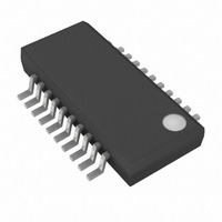
MAX1714AEEP Maxim Integrated Products, MAX1714AEEP Datasheet - Page 15

MAX1714AEEP
Manufacturer Part Number
MAX1714AEEP
Description
IC CTRLR HS STEPDOWN 20-QSOP
Manufacturer
Maxim Integrated Products
Type
Step-Down (Buck)r
Datasheet
1.MAX1714AEEP.pdf
(24 pages)
Specifications of MAX1714AEEP
Internal Switch(s)
No
Synchronous Rectifier
Yes
Number Of Outputs
1
Voltage - Output
2.5V, 3.3V, Adj
Current - Output
8A
Frequency - Switching
600kHz
Voltage - Input
2 ~ 28 V
Operating Temperature
-40°C ~ 85°C
Mounting Type
Surface Mount
Package / Case
20-QSOP
Power - Output
727mW
Output Voltage
1 V to 5.5 V
Output Current
3000 mA
Mounting Style
SMD/SMT
Switching Frequency
600 KHz
Maximum Operating Temperature
+ 85 C
Minimum Operating Temperature
- 40 C
Synchronous Pin
No
Topology
Buck
Case
SSOP20
Dc
04+
Lead Free Status / RoHS Status
Contains lead / RoHS non-compliant
Available stocks
Company
Part Number
Manufacturer
Quantity
Price
Part Number:
MAX1714AEEP
Manufacturer:
MAXIM/美信
Quantity:
20 000
Company:
Part Number:
MAX1714AEEP+
Manufacturer:
Maxim Integrated Products
Quantity:
135
Company:
Part Number:
MAX1714AEEP+
Manufacturer:
ISSI
Quantity:
7 229
Part Number:
MAX1714AEEP+
Manufacturer:
MAXIM/美信
Quantity:
20 000
Company:
Part Number:
MAX1714AEEP+T
Manufacturer:
MAXM
Quantity:
7 341
Company:
Part Number:
MAX1714AEEP-T
Manufacturer:
ISSI
Quantity:
6 816
Part Number:
MAX1714AEEP-T
Manufacturer:
MAXIM/美信
Quantity:
20 000
2) Maximum load current. There are two values to con-
3) Switching frequency. This choice determines the
Figure 6. Disabling Over/Undervoltage Protection
(No-Fault Test Mode)
Table 3. Operating Mode Truth Table
SHDN
( ) ARE FOR THE MAX1714B ONLY.
0
1
1
1
1
sider. The peak load current (I
the instantaneous component stresses and filtering
requirements, and thus drives output capacitor selec-
tion, inductor saturation rating, and the design of the
current-limit circuit. The continuous load current
(I
ves the selection of input capacitors, MOSFETs, and
other critical heat-contributing components. Modern
notebook CPUs generally exhibit:
basic trade-off between size and efficiency. The opti-
mal frequency is largely a function of maximum input
LOAD
AGND
AGND Switching
Below
SKIP
V
) determines the thermal stresses and thus dri-
X
CC
X
I
LOAD
Switching
Switching
High
High
DL
______________________________________________________________________________________
MAX1714
= I
LOAD(MAX)
(GND)
AGND
Run (PWM),
(PFM/PWM)
Low Noise
Shutdown
No Fault
MODE
Fault
Run
SKIP
LOAD(MAX)
High-Speed Step-Down Controller
· 80%
APPROXIMATELY
1.5mA
Low-power shutdown state. DL is forced to V
Test mode with OVP, UVP, and thermal faults disabled and latches cleared. Otherwise
normal operation, with automatic PWM/PFM switchover for pulse skipping at light loads
(Figure 6).
Low-noise operation with no automatic switchover. Fixed-frequency PWM action is
forced regardless of load. Inductor current reverses at light load levels. Low noise,
high I
Normal operation with automatic PWM/PFM switchover for pulse skipping at light loads.
Best light-load efficiency.
Fault latch has been set by OVP, output UVLO, or thermal shutdown. Device will remain
in FAULT mode until V
SHDN is toggled.
-0.65V
) determines
Q
.
V
FORCE
for Notebook Computers
CC
4) Inductor operating point. This choice provides
These four factors impact the component selection
process. Selecting components and calculating their
effect on the MAX1714’s operation is best done with a
spreadsheet. Using the formulas provided, calculate the
LIR (the ratio of the inductor ripple current to the
designed maximum load current) for both the minimum
and maximum input voltages. Maintaining an LIR within a
20% to 50% range is prudent. The use of a spreadsheet
allows quick evaluation of component selection.
power is cycled, SKIP is forced below ground (Figure 6), or
voltage, due to MOSFET switching losses that are
proportional to frequency and V
quency is also a moving target, due to rapid improve-
ments in MOSFET technology that are making higher
frequencies more practical (Table 4).
trade-offs between size vs. efficiency. Low inductor
values cause large ripple currents, resulting in the
smallest size, but poor efficiency and high output rip-
ple. The minimum practical inductor value is one that
causes the circuit to operate at the edge of critical
conduction (where the inductor current just touches
zero with every cycle at maximum load). Inductor val-
ues lower than this grant no further size-reduction
benefit.
The MAX1714’s pulse-skipping algorithm initiates skip
mode at the critical conduction point. So, the inductor
operating point also determines the load-current value
at which PFM/PWM switchover occurs.
COMMENTS
DD
, enforcing OVP. I
IN 2
CC
. The optimum fre-
< 1µA typ.
15


