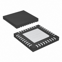
MAX8654ETX+ Maxim Integrated Products, MAX8654ETX+ Datasheet - Page 11

MAX8654ETX+
Manufacturer Part Number
MAX8654ETX+
Description
IC REG STP DWN 12V 8A 36TQFN
Manufacturer
Maxim Integrated Products
Type
Step-Down (Buck)r
Datasheet
1.MAX8654ETX.pdf
(17 pages)
Specifications of MAX8654ETX+
Internal Switch(s)
Yes
Synchronous Rectifier
No
Number Of Outputs
1
Voltage - Output
0.6 ~ 11.9 V
Current - Output
8A
Frequency - Switching
250kHz ~ 1.2MHz
Voltage - Input
4.5 ~ 14 V
Operating Temperature
-40°C ~ 85°C
Mounting Type
Surface Mount
Package / Case
36-TQFN Exposed Pad
Power - Output
2.86W
Output Voltage
0.6 V to 0.85 V
Output Current
8 A
Input Voltage
4.5 V to 14 V
Switching Frequency
1 MHz
Operating Temperature Range
- 40 C to + 85 C
Mounting Style
SMD/SMT
Lead Free Status / RoHS Status
Lead free / RoHS Compliant
The controller logic block is the central processor that
determines the duty cycle of the high-side MOSFET
under different line, load, and temperature conditions.
Under normal operation, where the current-limit and
temperature protection are not triggered, the controller
logic block takes the output from the PWM comparator
and generates the driver signals for both high-side and
low-side MOSFETs. The break-before-make logic and
the timing for charging the bootstrap capacitors are
calculated by the controller logic block. The error signal
from the voltage-error amplifier is compared with the
ramp signal generated by the oscillator at the PWM
comparator, and thus the required PWM signal is pro-
duced. The high-side switch is turned on at the begin-
ning of the oscillator cycle and turns off when the ramp
voltage exceeds the V
limit threshold is exceeded. The low-side switch is then
turned on for the remainder of the oscillator cycle.
The MAX8654 adjustable current limit is set by a resis-
tor, R
through R
where I
R
ical peak current limit of 8A, sourcing or sinking at LX.
When current flowing out of LX exceeds this limit,
the high-side MOSFET turns off and the synchronous
rectifier turns on. The synchronous rectifier remains on
until the inductor current falls below the low-side cur-
rent limit. This lowers the duty cycle and causes the
output voltage to drop until the current limit is no longer
exceeded.
When the negative current limit is exceeded, the device
turns off the synchronous rectifier, forcing the inductor
current to flow through the high-side MOSFET body
diode, back to the input, until the beginning of the next
cycle, or until the inductor current drops to zero.
The MAX8654 uses a hiccup mode to prevent overheat-
ing during short-circuit output conditions. The device
enters hiccup mode when V
more than 12µs, pulling COMP and REFIN low. The IC
turns off for 900 clock cycles and then enters soft-start
for 110 clock cycles. If the short-circuit condition
remains, the IC shuts down for another 512 clock
cycles. The IC repeats this behavior until the short-cir-
cuit condition is removed.
ILIM
ILIM
range is 40kΩ to 200kΩ. R
LXLIM
, connected from ILIM to GND. The current
ILIM
R
is the LX current-limit threshold. The valid
determines the LX current-limit trip point:
ILIM
______________________________________________________________________________________
(kΩ) = 800 / I
COMP
signal or when the current-
FB
Controller Function
ILIM
drops below 420mV for
LXLIM
of 100kΩ sets a typ-
Current Limit
(A)
The MAX8654 utilizes an adjustable soft-start function
to limit inrush current during startup. An 8µA (typ) cur-
rent source charges an external capacitor connected to
SS to increase the capacitor voltage in a controlled
manner. The soft-start time is adjusted by the value of
the external capacitor from SS to GND. The required
capacitance value is determined as:
where t
The MAX8654 also features an external reference input
(REFIN). The IC regulates FB to the voltage applied to
REFIN. The internal soft-start is not available when
using an external reference. A method of soft-start
when using an external reference is shown in Figure 2.
When using an external reference, in order to avoid cur-
rent limit during soft-start, care should be taken to
ensure the following condition:
where I
output capacitance, and I
tor ripple current.
Connect REFIN to SS to use the internal 0.6V reference.
Figure 2. Typical Soft-Start Implementation with External
Reference
Step-Down Regulator
SS
OUT
C
is the required soft-start time in seconds.
OUT
R1
is the maximum output current, C
R2
×
dV
12V, 8A 1.2MHz
REFIN
dt
C
C
=
8
P-P
μ
+
A t
0 6
I
OUT
.
REFIN
Soft-Start and REFIN
×
is the peak-to-peak induc-
V
SS
MAX8654
<
I
LXLIM
−
I
P P
2
−
OUT
is the
11


