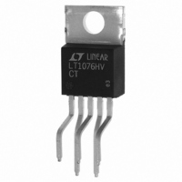
LT1076HVCT Linear Technology, LT1076HVCT Datasheet - Page 9

LT1076HVCT
Manufacturer Part Number
LT1076HVCT
Description
IC SWTCHNG REG STP-DWN 2A TO-220
Manufacturer
Linear Technology
Type
Step-Down (Buck), Step-Up (Boost), Inverting, Flybackr
Datasheet
1.LT1076CTPBF.pdf
(16 pages)
Specifications of LT1076HVCT
Internal Switch(s)
Yes
Synchronous Rectifier
No
Number Of Outputs
1
Voltage - Output
2.5 ~ 50 V
Current - Output
2A
Frequency - Switching
100kHz
Voltage - Input
8 ~ 64 V
Operating Temperature
0°C ~ 70°C
Mounting Type
Through Hole
Package / Case
TO-220-5 (Bent and Staggered Leads)
Lead Free Status / RoHS Status
Contains lead / RoHS non-compliant
Power - Output
-
Available stocks
Company
Part Number
Manufacturer
Quantity
Price
Company:
Part Number:
LT1076HVCT
Manufacturer:
LT
Quantity:
5 510
Part Number:
LT1076HVCT
Manufacturer:
LT/凌特
Quantity:
20 000
Part Number:
LT1076HVCT7-5#PBF
Manufacturer:
LINEAR/凌特
Quantity:
20 000
PI
current is well controlled even when switch duty cycle
must be extremely low. Theoretical switch “on” time for a
buck converter in continuous mode is:
At f = 100kHz, t
and the output is shorted (V
the LT1074 can reduce t
≈0.6µs, much too long to control current correctly for
V
is lowered from 100kHz to 20kHz as the FB pin drops
from 1.3V to 0.5V. This is accomplished by the circuitry
shown in Figure 3.
Q1 is off when the output is regulating (V
the output is pulled down by an overload, V
ally reach 1.3V, turning on Q1. As the output continues to
drop, Q1 current increases proportionately and lowers the
frequency of the oscillator. Frequency shifting starts when
the output is ≈ 60% of normal value, and is down to its
minimum value of ≅ 20kHz when the output is ≅ 20% of
normal value. The rate at which frequency is shifted is
determined by both the internal 3k resistor R3 and the
external divider resistors. For this reason, R2 should not
be increased to more than 4kΩ, if the LT1074 will be
subjected to the simultaneous conditions of high input
voltage and output short-circuit.
OUT
V
f = Switching frequency
t
U
ON
D
V
= 0. To correct this problem, switching frequency
C
= Catch diode forward voltage ( ≈ 0.5V)
DESCRIPTIO S
=
V
OUT
V
AMPLIFIER
IN
ERROR
+
•
Figure 3. Frequency Shifting
ON
f
V
D
+
–
must drop to 0.2µs when V
+2V
2.21V
U
ON
OUT
Q1
R3
3k
to a minimum value of
FB
TO
OSCILLATOR
= 0V). In current limit,
R1
R2
2.21k
V
FB
OUT
FB
= 2.21V). As
EXTERNAL
DIVIDER
will eventu-
LT1074•PD03
IN
= 25V
SHUTDOWN PIN
The shutdown pin is used for undervoltage lockout, micro-
power shutdown, soft-start, delayed start, or as a general
purpose on/off control of the regulator output. It controls
switching action by pulling the I
the switch to a continuous “off” state. Full micropower
shutdown is initiated when the shutdown pin drops below
0.3V.
The V/I characteristics of the shutdown pin are shown in
Figure 4. For voltages between 2.5V and ≈V
10µA flows out of the shutdown pin. This current in-
creases to ≈25µA as the shutdown pin moves through the
2.35V threshold. The current increases further to ≈30µA at
the 0.3V threshold, then drops to ≈15µA as the shutdown
voltage fall below 0.3V. The 10µA current source is in-
cluded to pull the shutdown pin to its high or default state
when left open. It also provides a convenient pull-up for
delayed start applications with a capacitor on the shut-
down pin.
When activated, the typical collector current of Q1 in
Figure 5, is ≈2mA. A soft-start capacitor on the I
delay regulator shutdown in response to C1, by
≈(5V)(C
down is ensured by coupling C2 to Q1.
LIM
)/2mA. Soft-start after full micropower shut-
–10
–15
–20
–25
–30
–35
–40
Figure 4. Shutdown Pin Characteristics
–5
0
0
0.5
CURRENT FLOWS OUT
T
j
OF SHUTDOWN PIN
= 25°C
SHUTDOWN
THRESHOLD
1.0
1.5
VOLTAGE (V)
LT1074/LT1076
2.0
LIM
2.5
pin low, which forces
3.0
LT1074•PC05
3.5
IN
4.0
, a current of
LIM
sn1074 1074fds
pin will
9


