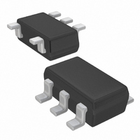
XC9133B02AMR-G Torex Semiconductor Ltd, XC9133B02AMR-G Datasheet - Page 8

XC9133B02AMR-G
Manufacturer Part Number
XC9133B02AMR-G
Description
IC BOOST ADJ .26A SOT25-5
Manufacturer
Torex Semiconductor Ltd
Type
Step-Up (Boost)r
Datasheet
1.XC9133B02AMR-G.pdf
(15 pages)
Specifications of XC9133B02AMR-G
Internal Switch(s)
Yes
Synchronous Rectifier
No
Number Of Outputs
1
Voltage - Output
2.5 ~ 17.5 V
Current - Output
260mA
Frequency - Switching
1MHz
Voltage - Input
2.5 ~ 6 V
Operating Temperature
-40°C ~ 85°C
Mounting Type
Surface Mount
Package / Case
SOT-23-5, SC-74A, SOT-25
Power - Output
250mW
Lead Free Status / RoHS Status
Lead free / RoHS Compliant
Available stocks
Company
Part Number
Manufacturer
Quantity
Price
Part Number:
XC9133B02AMR-G
Manufacturer:
TOREX
Quantity:
20 000
8/15
<Dimming Control (Continued)>
3. Using DC Voltage
<Prevent Emission Caused by White LEDs Leakage>
■APPLICATION INFORMATION (Continued)
If in an application it is necessary to control the LED current by a variable DC voltage, illumination control of LED is
achieved by connecting R1 and R2 and applying a direct-current voltage to R2, as shown below.
When R1>>R
When the input voltage (V
happens, please connect a transistor to between the LED and the FB pin. By driving the CE signal in-phase and cutting
the pass to current, the minimum illumination can be prevented.
I
V
XC9133
LED
Ex.1) When R1 = 10k
Ex.2) When R1 = 10k
REF
= 0.2V (TYP.)
In the range of 0.2V to 2.2V DC, I
(LED current) varies between 20mA to 0mA.
= (V
C1 = 0.1μF, RLED = 10Ω, the average LED current will
be 10mA by inputting a PWM signal of CE ‘H’ level:
2.2V, CE ’L’ level: 0V, duty cycle: 50%, oscillation
frequency: 100Hz. As well as the way of dimming
control by applying the PWM signal to the CE pin, the
average LED current increases proportionally with the
positive duty cycle of the PWM signal.
(3.2V~6.0V)
V
REF
IN
LED
3.6V
Figure
- R1 / R2 (V
4.7μF
, I
C
LED
IN
Series
which flows into LEDs can be calculated by the following equation;
Ω
Ω
Circuit Prevent Emission Caused by White LEDs Leakage
, R2 = 100k
, R2 = 100k
IN
DC
) is high, minimum illumination may occur even if the CE pin is in the disable state. If this
- V
REF
CE
V
IN
Ω
Ω
)) / R
VLF3010A
L:22μH
, R
, R3 = 10k
LED
V
LED
SS
LED
= 10
FB
Lx
XBS053V15R
Ω
Ω
,
,
SBD
10Ω
R
LED
XP151A12A2
20mA
Figure
Figure
0.22μF
(base)
V
C
DC
L
Circuit inputting a PWM signal to the FB pin
Circuit using DC voltage
R
2
XC9133
FB
R
I
LED
1
R
LED


