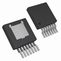
LM22678TJ-ADJ/NOPB National Semiconductor, LM22678TJ-ADJ/NOPB Datasheet - Page 10

LM22678TJ-ADJ/NOPB
Manufacturer Part Number
LM22678TJ-ADJ/NOPB
Description
IC REG SWITCH BUC 5A ADJ TO263-7
Manufacturer
National Semiconductor
Series
SIMPLE SWITCHER®r
Type
Step-Down (Buck)r
Datasheet
1.LM22678TJE-ADJNOPB.pdf
(16 pages)
Specifications of LM22678TJ-ADJ/NOPB
Internal Switch(s)
Yes
Synchronous Rectifier
No
Number Of Outputs
1
Voltage - Output
Adj to 1.285V
Current - Output
5A
Frequency - Switching
500kHz
Voltage - Input
4.5 ~ 42 V
Operating Temperature
-40°C ~ 125°C
Mounting Type
Surface Mount
Package / Case
TO-263-7 Thin
No. Of Outputs
1
Output Current
5A
No. Of Pins
7
Operating Temperature Range
-40°C To +125°C
Msl
MSL 1 - Unlimited
Peak Reflow Compatible (260 C)
Yes
Leaded Process Compatible
Yes
Rohs Compliant
Yes
For Use With
551600233-001 - WEBENCH BUILD IT LM2267X TO-263
Lead Free Status / RoHS Status
Lead free / RoHS Compliant
Power - Output
-
Other names
LM22678TJ-ADJ
Available stocks
Company
Part Number
Manufacturer
Quantity
Price
Company:
Part Number:
LM22678TJ-ADJ/NOPB
Manufacturer:
TI
Quantity:
4 000
Company:
Part Number:
LM22678TJ-ADJ/NOPB
Manufacturer:
Texas Instruments
Quantity:
500
Part Number:
LM22678TJ-ADJ/NOPB
Manufacturer:
TI/德州仪器
Quantity:
20 000
www.national.com
-5.0 option:
Where V
-5.0 option
A maximum value of 10 kΩ is recommended for the sum of
R1 and R2 to keep high output voltage accuracy for the –ADJ
option. A maximum of 2 kΩ is recommended for the -5.0 out-
put voltage option. For the 5V fixed output voltage option, the
total internal divider resistance is typically 9.93 kΩ.
At loads less than 5 mA, the boot capacitor will not hold
enough charge to power the internal high side driver. The
FB
FIGURE 3. Resistive Feedback Divider
= 1.285V typical for the -ADJ option and 5V for the
30076123
10
output voltage may droop until the boot capacitor is
recharged. Selecting a total feedback resistance to be below
3 kΩ will provide some minimal load and can keep the output
voltage from collapsing in such low load conditions.
Catch Diode
A Schottky type re-circulating diode is required for all
LM22678 applications. Ultra-fast diodes which are not Schot-
tky diodes are not recommended and may result in damage
to the IC due to reverse recovery current transients. The near
ideal reverse recovery characteristics and low forward volt-
age drop of Schottky diodes are particularly important diode
characteristics for high input voltage and low output voltage
applications common to the LM22678. The reverse recovery
characteristic determines how long the current surge lasts
each cycle when the N-channel MOSFET is turned on. The
reverse recovery characteristics of Schottky diodes mini-
mizes the peak instantaneous power in the switch occurring
during turn-on for each cycle. The resulting switching losses
are significantly reduced when using a Schottky diode. The
reverse breakdown rating should be selected for the maxi-
mum V
a diode with the reverse voltage rating of 1.3 times the max-
imum input voltage.
The forward voltage drop has a significant impact on the con-
version efficiency, especially for applications with a low output
voltage. ‘Rated’ current for diodes varies widely from various
manufacturers. The worst case is to assume a short circuit
load condition. In this case the diode will carry the output cur-
rent almost continuously. For the LM22678 this current can
be as high as 7.1A (typical). Assuming a worst case 1V drop
across the diode, the maximum diode power dissipation can
be as high as 7.1W.
IN
, plus some safety margin. A rule of thumb is to select


