LM27213MTD/NOPB National Semiconductor, LM27213MTD/NOPB Datasheet
LM27213MTD/NOPB
Specifications of LM27213MTD/NOPB


Related parts for LM27213MTD/NOPB

LM27213MTD/NOPB Summary of contents
Page 1
... The LM27213 also has a soft start feature for the external adjustment of soft start speed. Typical Application © 2006 National Semiconductor Corporation Features n Ideal load and line transient responses 30V input range n On-chip gate drive ...
Page 2
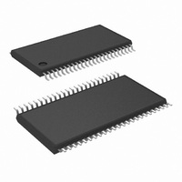
Connection Diagrams Top View 48-Lead TSSOP (MTD) See NS Package Number MTD48 Ordering Information Order Number LM27213MTD LM27213MTDX LM27213SQ LM27213SQX www.national.com 20154301 NS Package Number SQA48A Package Drawing MTD48 MTD48 1000 Units Tape and Reel SQA48A 1000 Units Tape and ...
Page 3
Pin Descriptions (TSSOP/LLP) Pin 1, CBOOT: Connection for the high-side drive bootstrap capacitor. Pin 2, HG: High-side FET gate drive output. Pin 3, SW: Connect to switch node (drain of bottom power FET) to detect inductor current reversal. Also serves ...
Page 4
VID ...
Page 5
... Absolute Maximum Ratings If Military/Aerospace specified devices are required, please contact the National Semiconductor Sales Office/ Distributors for availability and specifications. VDD, DVDD XPOK, VR_ON, DE_EN#, VOVP, VBOOT, VID0 to VID5, STP_CPU#, SLP, VSLP, VSTP, SENSE, CMP1, CMP2, CMPREF, ILIM1, ILIM2, ILIMREF PGOOD ...
Page 6
Electrical Characteristics type apply over a junction temperature range of -5˚C to +110˚C. Unless otherwise specified, VDD = 5V, SGND = DGND = PGND = SRCK = 0V, unless otherwise stated. (Note 5) (Continued) Symbol Parameter V DAC Accuracy dac ...
Page 7
... The LM27213 actively limits its junction temperature to about 150˚C. Note 3: For detailed information on soldering plastic small-outline packages, refer to the Packaging Databook available from National Semiconductor Corporation. Note 4: For testing purposes, ESD was applied using the human-body model, a 100pF capacitor discharged through a 1.5kΩ resistor. ...
Page 8
Typical Application www.national.com 8 20154304 ...
Page 9
Block Diagram 9 20154303 www.national.com ...
Page 10
Typical Performance Characteristics Turn-On Waveforms Ch1: V OUT Ch3: VRON 13V OUT Turn-Off Waveforms Ch1: V OUT Ch 3: VRON Ch 4: PGOOD Start-Up, VBOOT to VID Transition Ch1: V OUT Ch2: CLK_EN# Ch ...
Page 11
Typical Performance Characteristics Light Load, Diode Emulator Mode Ch1: Switch Node Ch2: VID5 OUT ILIMREF Bias 25˚C IN ILIM vs Temperature (Continued) LM29213 Typical Efficiency 20154311 Hysteresis Current vs V 20154313 Hysteresis Current vs ...
Page 12
Typical Performance Characteristics DAC 100100 (1.32V) vs Temperature DAC 100100 vs V www.national.com (Continued) UVLO Rising Threshold vs Temperature 20154317 UVLO Falling Threshold vs Temperature IN 20154319 12 20154318 20154320 ...
Page 13
Applications Information The LM27213 is a single phase current-mode hysteretic controller intended for controlling a power supply for a low voltage CPU core capable of currents up to approxi- mately 25A with conventional surface mount power devices. Hysteretic ...
Page 14
Applications Information FIGURE 2. Figure 3 below shows the theoretical waveform that expected at the CMP pin. Zero output ripple voltage is as- sumed. In reality these signals ride on top of the regulator’s output ripple and ...
Page 15
Applications Information simply 20µA divided by the desired slew rate. For an output voltage rate of rise of 1V/ms, the capacitor should be about 20nF. SOFT STOP When VRON is deasserted, the LM27213 starts to discharge the soft start capacitor ...
Page 16
Component Selection L = 0.60 µH If the switching frequency is pushed up a bit the inductor value may be reduced accordingly. In general for a 12A, low voltage CPU, a value between 0.56 µH and 0.7 µH works out ...
Page 17
Component Selection A simulation of the above conditions with the addition of 10 pieces of a 22µF ceramic capacitor yields a peak excursion of 1.180V, which is well within the specified limit. MOSFET SELECTION The choice of power FETs is ...
Page 18
Component Selection FIGURE 4. RMS Input Ripple Current as a Percentage of DC Output Current So for a design that must operate at a steady state load current of 12A, with 1.4V out and 8V in, the RMS input ripple ...
Page 19
Layout Guidelines (Continued) Keep the switch node connection between the two FETs and the inductor as short and wide as possible. The inductor should be located very close to the FETs. The inductor should then flow in to the sense ...
Page 20
Layout Guidelines (Continued) The circuit above is an example of a single phase supply at much higher current. The FETs chosen lend themselves well to the use of a heatsink if desired. The transient response is quite good for a ...
Page 21
Physical Dimensions inches (millimeters) unless otherwise noted 48-Lead TSSOP Package Order Number LM27213MTD NS Package Number MTD48 48-Lead LLP Package Order Number LM27213SQ NS Package Number SQA48A 21 www.national.com ...
Page 22
... BANNED SUBSTANCE COMPLIANCE National Semiconductor manufactures products and uses packing materials that meet the provisions of the Customer Products Stewardship Specification (CSP-9-111C2) and the Banned Substances and Materials of Interest Specification (CSP-9-111S2) and contain no ‘‘Banned Substances’’ as defined in CSP-9-111S2. ...