PC512J00000F Sharp Microelectronics, PC512J00000F Datasheet
PC512J00000F
Specifications of PC512J00000F


Related parts for PC512J00000F


PC512J00000F Summary of contents
Page 1
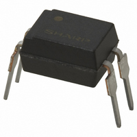
PC512 ■ Description PC512 contains an IRED optically coupled to a pho- totransistor packaged pin case type. Input-output isolation voltage(rms) is 5.0kV. Collector-emitter voltage is 35V ■ Features 1. 4 pin case type package 2. ...
Page 2
Internal Connection Diagram 1 2 ■ Outline Dimensions C0.7 ±0.2 16.2 PC5 12 Factory Identification mark Rank mark Date code 4-0.4 (12. Reference dimensions Anode 1 4 Cathode 2 Collector 3 3 Emitter 4 ...
Page 3
Date code (2 digit) 1st digit Year of production A.D. Mark A.D Mark 1990 A 2002 P 1991 B 2003 R 1992 C 2004 S 1993 D 2005 T 1994 E 2006 U 1995 F 2007 V 1996 H 2008 ...
Page 4
Absolute Maximum Ratings Parameter Symbol Forward current Peak forward current I FM Reverse voltage V R Power dissipation P Collector-emitter voltage V CEO Emitter-collector voltage V ECO Collector current I C Collector power dissipation P C ...
Page 5
Fig.1 Forward Current vs. Ambient Temperature − Ambient temperature T Fig.3 Peak Forward Current vs. Duty Ratio Pulse width≤100µ 000 a 1 000 100 10 −3 −2 10 ...
Page 6
Fig.7 Relative Current Transfer Ratio vs. Ambient Temperature 150 100 50 0 − Ambient temperature T Fig.9 Collector Dark Current vs. Ambient Temperature −6 10 =20V V CE −7 10 −8 10 −9 10 − ...
Page 7
Fig.13 Test Circuit for Frequency Response R D Please refer to the conditions in Fig.12 Remarks : Please be aware that all data in the graph are just for reference and not for guarantee. Fig.14 Collector-emitter Saturation Voltage vs. Forward ...
Page 8
Design Considerations ● Design guide While operating at I <5.0mA, CTR variation may increase. F Please make design considering this fact. This product is not designed against irradiation and incorporates non-coherent IRED. ● Degradation In general, the emission of ...
Page 9
Manufacturing Guidelines ● Soldering Method Hand soldering Hand soldering should be completed within 3s when the point of solder iron is below 400˚C. Please don't solder more than twice. Please don't bend lead pins from the root of package ...
Page 10
Package specification Package materials Plastic bag : Polyethylene Moltopren : Urethane Packing case : Corrugated fiberboard Package method 25 pcs of products shall be packaged in a plastic bag. Ends shall be fixed by stoppers. The bottom of the ...
Page 11
Important Notices · The circuit application examples in this publication are provided to explain representative applications of SHARP devices and are not intended to guarantee any circuit design or license any intellectual property rights. SHARP takes no responsibility for ...