LTL2T3TBK4 Lite-On Electronics, LTL2T3TBK4 Datasheet - Page 3
LTL2T3TBK4
Manufacturer Part Number
LTL2T3TBK4
Description
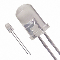
LED 5MM 468NM BLUE WATER CLEAR
Manufacturer
Lite-On Electronics
Datasheet
1.LTL2T3TBK4.pdf
(8 pages)
Specifications of LTL2T3TBK4
Viewing Angle
30°
Package / Case
Radial - 2 Lead
Color
Blue
Millicandela Rating
680mcd
Current - Test
20mA
Wavelength - Dominant
470nm
Wavelength - Peak
468nm
Voltage - Forward (vf) Typ
3.5V
Lens Type
Clear
Lens Style/size
Round, 5mm, T-1 3/4
Height
8.70mm
Mounting Type
Through Hole
Resistance Tolerance
470nm
Led Size
T-1 3/4
Illumination Color
Blue
Lens Color/style
Water Clear
Operating Voltage
3.8 V
Wavelength
468 nm
Luminous Intensity
680 mcd
Operating Current
100 mA
Lens Shape
Dome
Mounting Style
Through Hole
Lead Free Status / RoHS Status
Lead free / RoHS Compliant
Luminous Flux @ Current - Test
-
Lead Free Status / RoHS Status
Lead free / RoHS Compliant, Lead free / RoHS Compliant
Other names
160-1609
Available stocks
Company
Part Number
Manufacturer
Quantity
Price
Company:

Part Number:
LTL2T3TBK4
Manufacturer:
LITEON
Quantity:
40 000


NOTE: 1. Luminous intensity is measured with a light sensor and filter combination that approximates the CIE
BNS-OD-C131/A4
Part No. : LTL2T3TBK4
Electrical / Optical Characteristics at T
Luminous Intensity
Viewing Angle
Peak Emission Wavelength
Dominant Wavelength
Spectral Line Half-Width
Forward Voltage
Reverse Current
2. θ
3. The dominant wavelength, λd is derived from the CIE chromaticity diagram and represents the single
4. Iv classification code is marked on each packing bag.
5. The Iv guarantee should be added ± 15% tolerance.
6. Precautions in handling:
7. Caution in ESD:
eye-response curve.
wavelength which defines the color of the device.
glove when handling the LED. All devices, equipment and machinery must be properly grounded.
• When soldering, leave 2mm of minimum clearance from the resin to the soldering point.
• Dipping the resin to solder must be avoided.
• Correcting the soldered position after soldering must be avoided.
• In soldering, do not apply any stress to the lead frame particularly when heated.
• When forming a lead, make sure not to apply any stress inside the resin.
• Lead forming must be done before soldering.
• It is necessary to cut the lead frame at normal temperature.
Static Electricity and surge damages the LED. It is recommend to use a wrist band or anti-electrostatic
1/2
Parameter
is the off-axis angle at which the luminous intensity is half the axial luminous intensity.
LITE-ON TECHNOLOGY CORPORATION
Symbol
2 θ
Δλ
λ
λ
V
I
I
V
R
F
1/2
P
d
P r o p e r t y o f L i t e - O n O n l y
Min.
240
A
=25 ℃
Typ.
680
468
470
3.5
30
25
Max.
100
3.8
Page : 3
Unit
mcd
μ A
deg
nm
nm
nm
V
I
Note 1,5
Note 2 (Fig.6)
Measurement
@Peak (Fig.1)
Note 3
I
V
F
F
Test Condition
R
= 20mA
= 20mA
= 5V
of
8
Related parts for LTL2T3TBK4
Image
Part Number
Description
Manufacturer
Datasheet
Request
R

Part Number:
Description:
Photodiodes Phototrans Filtered
Manufacturer:
Lite-On Electronics
Datasheet:

Part Number:
Description:
ENCODER/DECODER 3/16 8-SOIC
Manufacturer:
Lite-On Electronics
Datasheet:

Part Number:
Description:
OPTOCOUPLER HS LOGIC OUT 8-DIP
Manufacturer:
Lite-On Electronics
Datasheet:

Part Number:
Description:
OPTOCOUPLER HS TRANS OUT 8-DIP
Manufacturer:
Lite-On Electronics
Datasheet:

Part Number:
Description:
OPTOCOUPLER HS TRANS OUT 8-SMD
Manufacturer:
Lite-On Electronics
Datasheet:

Part Number:
Description:
OPTOCOUPLER HS TRANS OUT 8-DIP
Manufacturer:
Lite-On Electronics
Datasheet:

Part Number:
Description:
OPTOCOUPLER HS LOGIC OUT 8-SMD
Manufacturer:
Lite-On Electronics
Datasheet:

Part Number:
Description:
OPTOCOUPLER HS TRANS OUT 8-SMD
Manufacturer:
Lite-On Electronics
Datasheet:

Part Number:
Description:
OPTOISOLATOR 1CH 4-DIP
Manufacturer:
Lite-On Electronics
Datasheet:

Part Number:
Description:
OPTOISOLATOR W/BASE 6-DIP
Manufacturer:
Lite-On Electronics
Datasheet:
Part Number:
Description:
OPTOISOLATOR W/BASE 6-DIP
Manufacturer:
Lite-On Electronics
Datasheet:
Part Number:
Description:
OPTOISOLATOR W/BASE 6-DIP
Manufacturer:
Lite-On Electronics
Datasheet:
Part Number:
Description:
OPTOISOLATOR W/O BASE 6-DIP
Manufacturer:
Lite-On Electronics
Datasheet:
Part Number:
Description:
OPTOISOLATOR W/O BASE 6-DIP
Manufacturer:
Lite-On Electronics
Datasheet:
Part Number:
Description:
OPTOISOLATOR W/BASE 6-DIP
Manufacturer:
Lite-On Electronics
Datasheet: