LTL2T3TBK4 Lite-On Electronics, LTL2T3TBK4 Datasheet - Page 7
LTL2T3TBK4
Manufacturer Part Number
LTL2T3TBK4
Description
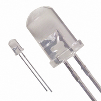
LED 5MM 468NM BLUE WATER CLEAR
Manufacturer
Lite-On Electronics
Datasheet
1.LTL2T3TBK4.pdf
(8 pages)
Specifications of LTL2T3TBK4
Viewing Angle
30°
Package / Case
Radial - 2 Lead
Color
Blue
Millicandela Rating
680mcd
Current - Test
20mA
Wavelength - Dominant
470nm
Wavelength - Peak
468nm
Voltage - Forward (vf) Typ
3.5V
Lens Type
Clear
Lens Style/size
Round, 5mm, T-1 3/4
Height
8.70mm
Mounting Type
Through Hole
Resistance Tolerance
470nm
Led Size
T-1 3/4
Illumination Color
Blue
Lens Color/style
Water Clear
Operating Voltage
3.8 V
Wavelength
468 nm
Luminous Intensity
680 mcd
Operating Current
100 mA
Lens Shape
Dome
Mounting Style
Through Hole
Lead Free Status / RoHS Status
Lead free / RoHS Compliant
Luminous Flux @ Current - Test
-
Lead Free Status / RoHS Status
Lead free / RoHS Compliant, Lead free / RoHS Compliant
Other names
160-1609
Available stocks
Company
Part Number
Manufacturer
Quantity
Price
Company:

Part Number:
LTL2T3TBK4
Manufacturer:
LITEON
Quantity:
40 000


2. Storage
3. Cleaning
4. Forming & Mounting
5. Soldering
1. Application limitation
6. Drive Method
Part No. : LTL2T3TBK4
BNS-OD-C131/A4
After being shipped from Liteon the LEDs should be kept at 30°C or less and 70%RH or less.
The LEDs should be used within 3 months. They can be stored for a year in a sealed container with a nitrogen
atmosphere and moisture absorbent material. Please avoid rapid transitions in ambient temperature in high
humidity environments where condensation may occur.
Use alcohol-based cleaning solvents such as isopropyl alcohol to clean the LED.
When forming a lead, the leads should be bent at a point at least 3mm from the base of epoxy bulb. Do not use
the base of the leadframe as a fulcrum during forming. Lead forming must be done before soldering at normal
temperature. When mounted through hole type LED lamp, avoid the occurrence of residual mechanical stress
due to clinching as figure shown here.
When soldering, leave a minimum of 2mm clearance from the resin to the soldering point.
Dipping the resin into the solder must be avoided.
Do not apply any stress to the lead frame during soldering while the LED is at high temperature.
Recommended soldering condition
LED is a current operated device, and therefore, requires some kind of current limiting incorporated into the
drive circuit. This current limiting typically takes the form of a current limiter resistor placed in series with
the LED. Consider worst case voltage variations that could occur across the current limiting resistor.
The forward current should not be allowed to change by more than 40% of its desired value.
(A) Recommended circuit.
(B) The difference of brightness between LEDs could be found due to the Vf-If characteristics of LED
The LEDs described here are intended to be used for ordinary electronic equipment (such as office equipment,
communication equipment and household application.) Consult Liteon’s sales in advance for information on
application in which exceptional quality and reliability are required, particularly when the failure or malfunction
of the LEDs may directly jeopardize life or health (such as airplanes, automobiles, traffic control equipment, life
support system and safety devices).
Temperature
Soldering time
Circuit model A
Soldering iron
300°C Max.
3 sec. Max.
LED
(one time only)
LITE-ON TECHNOLOGY CORPORATION
P r o p e r t y o f L i t e - O n O n l y
Pre-heat
Pre-heat time
Solder wave
Soldering time
CAUTIONS
Circuit model B
Wave soldering
100°C Max.
60 sec. Max.
260°C Max.
10 sec. Max.
LED
Page :
7
of
8
Related parts for LTL2T3TBK4
Image
Part Number
Description
Manufacturer
Datasheet
Request
R

Part Number:
Description:
Photodiodes Phototrans Filtered
Manufacturer:
Lite-On Electronics
Datasheet:

Part Number:
Description:
ENCODER/DECODER 3/16 8-SOIC
Manufacturer:
Lite-On Electronics
Datasheet:

Part Number:
Description:
OPTOCOUPLER HS LOGIC OUT 8-DIP
Manufacturer:
Lite-On Electronics
Datasheet:

Part Number:
Description:
OPTOCOUPLER HS TRANS OUT 8-DIP
Manufacturer:
Lite-On Electronics
Datasheet:

Part Number:
Description:
OPTOCOUPLER HS TRANS OUT 8-SMD
Manufacturer:
Lite-On Electronics
Datasheet:

Part Number:
Description:
OPTOCOUPLER HS TRANS OUT 8-DIP
Manufacturer:
Lite-On Electronics
Datasheet:

Part Number:
Description:
OPTOCOUPLER HS LOGIC OUT 8-SMD
Manufacturer:
Lite-On Electronics
Datasheet:

Part Number:
Description:
OPTOCOUPLER HS TRANS OUT 8-SMD
Manufacturer:
Lite-On Electronics
Datasheet:

Part Number:
Description:
OPTOISOLATOR 1CH 4-DIP
Manufacturer:
Lite-On Electronics
Datasheet:

Part Number:
Description:
OPTOISOLATOR W/BASE 6-DIP
Manufacturer:
Lite-On Electronics
Datasheet:
Part Number:
Description:
OPTOISOLATOR W/BASE 6-DIP
Manufacturer:
Lite-On Electronics
Datasheet:
Part Number:
Description:
OPTOISOLATOR W/BASE 6-DIP
Manufacturer:
Lite-On Electronics
Datasheet:
Part Number:
Description:
OPTOISOLATOR W/O BASE 6-DIP
Manufacturer:
Lite-On Electronics
Datasheet:
Part Number:
Description:
OPTOISOLATOR W/O BASE 6-DIP
Manufacturer:
Lite-On Electronics
Datasheet:
Part Number:
Description:
OPTOISOLATOR W/BASE 6-DIP
Manufacturer:
Lite-On Electronics
Datasheet: