LSM2-T/6-D12-C Murata Power Solutions Inc, LSM2-T/6-D12-C Datasheet - Page 8
LSM2-T/6-D12-C
Manufacturer Part Number
LSM2-T/6-D12-C
Description
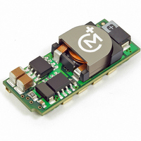
CONV DC/DC 30W 6A 12V SMD
Manufacturer
Murata Power Solutions Inc
Series
LSM2r
Type
Point of Load (POL) Non-Isolatedr
Datasheet
1.LSM2-T6-W3N-C.pdf
(17 pages)
Specifications of LSM2-T/6-D12-C
Output
0.75 ~ 5V
Number Of Outputs
1
Power (watts)
30W
Mounting Type
Surface Mount
Voltage - Input
8.3 ~ 13.2V
Package / Case
8-DIP SMD Module
1st Output
0.75 ~ 5 VDC @ 6A
Size / Dimension
1.30" L x 0.53" W x 0.34" H (33mm x 13.5mm x 8.6mm)
Power (watts) - Rated
30W
Operating Temperature
-40°C ~ 85°C
Efficiency
93.4%
Approvals
CSA, cUL, EN, UL
Dc / Dc Converter O/p Type
Variable
No. Of Outputs
1
Input Voltage
8.3V To 14V
Power Rating
30W
Output Voltage
5V
Output Current
6A
Approval Bodies
UL, CSA
Supply Voltage
12V
Dc / Dc Converter Case Style
SMD
Product
Non-Isolated / POL
Output Power
30 W
Input Voltage Range
10 V to 14 V
Output Voltage (channel 1)
0.75 V to 5 V
Output Current (channel 1)
6 A
Lead Free Status / RoHS Status
Lead free / RoHS Compliant
3rd Output
-
2nd Output
-
Lead Free Status / Rohs Status
Lead free / RoHS Compliant
Other names
811-1783-2


Don’t Use Pre-Biasing and Sequencing Together
Normally, you would use startup sequencing on multiple DC/DC’s to solve the
Pre-Bias problem. By causing all power sources to ramp up together, no one
source can dominate and force the others to fail to start. For most applica-
tions, do not use startup sequencing in a Pre-Bias application, especially with
an external active power source. If you have active source pre-biasing, leave
the Sequence input open so that the output will step up quickly and safely. A
symptom of this condition is repeated failed starts. You can further verify this
by removing the existing load and testing it with a separate passive resistive
load which does not exceed full current. If the resistive load starts successfully,
you may be trying to drive an external pre-biased active source.
Bias source is in fact only a small external bypass capacitor slowly charged by
leakage currents. Test your application to be sure.
Output Adjustments
The LSM2 series includes a special output voltage trimming feature which
is fully compatible with competitive units. The output voltage may be varied
using a single trim resistor from the Trim input to Power Common (pin 4) or an
external DC trim voltage applied between the Trim input and Power Common.
The output voltage range for W3 models is 0.75 to 3.3 Volts. For D12 models,
the output range is 0.75 to 5 Volts.
3.3 Volts maximum, the input supply must be 4.5 Volts minimum. To retain
proper regulation, do not exceed the 3.3V output.
resistor (±100 ppm/°C) mounted close to the converter with short leads. Also
be aware that the output voltage accuracy is ±2% (typical) therefore you may
need to vary this resistance slightly to achieve your desired output setting.
W3 Models Resistor Trim Equation:
V
R
It may also be possible to use pre-bias and sequencing together if the Pre-
IMPORTANT: On W3 models only, for outputs greater than 3 Volts up to
As with other trim adjustments, be sure to use a precision low-tempco
Two different trim equations are used for the W3 and D12 models.
The W3 models fi xed trim resistors to set the output voltage are:
OUT
TRIM
(Typ.)
R
(k:)
TRIM
(W) = _____________ – 5110
0.7525V
Open
V
O
80.021
– 0.7525
1.0V
21070
41.973
1.2V
23.077
1.5V
15.004
1.8V
6.947
2.5V
www.murata-ps.com
3.16
3.3V
D12 Models Resistor Trim Equation:
Voltage Trim
The LSM2 Series may also be trimmed using an external voltage applied
between the Trim input and Output Common. Be aware that the internal “load”
impedance looking into trim pin is approximately 5 Kilohms. Therefore, you
may have to compensate for this in the source resistance of your external volt-
age reference.
converter.
W3 Models Voltage Trim Equation:
D12 Models Voltage Trim Equation:
V
V
V
R
Use a low noise DC reference and short leads. Mount the leads close to the
Two different trim equations are used for the W3 and D12 models.
The LSM2 W3 fi xed trim voltages to set the output voltage are:
The LSM2 D12 fi xed trim voltages to set the output voltage are:
OUT
OUT
OUT
TRIM
V
V
TRIM
TRIM
(Typ.)
(Typ.)
R
(Typ.)
(k:)
TRIM
V
V
(W) = _____________ –1000
TRIM
TRIM
0.7525V
0.7525V
0.7525V
Open
Open
(in Volts) = 0.7 – (0.1698 x (V
(in Volts) = 0.7 – (0.0667 x (V
Open
Selectable-Output POL DC/DC Converters
V
O
0.6835 0.670
0.6928V
41.424
– 0.7525
1.0V
1.0V
1.0V
10500
25 Jun 2010
1.2V
22.46
1.2V
0.624V
1.2V
Single Output, Non-Isolated
0.650
1.5V
13.05
1.5V
0.5731V 0.5221V 0.4033V 0.267V
MDC_LSM2
1.5V
O
O
– 0.7525))
– 0.7525))
LSM2 Series
0.630
1.8V
email: sales@murata-ps.com
9.024
1.8V
1.8V
Series.B09Δ
0.583
2.5V
5.009
2.5V
2.5V
0.530 0.4166
3.3V
3.122 1.472
3.3V
Page 8 of 17
3.3V
5V
5V
Related parts for LSM2-T/6-D12-C
Image
Part Number
Description
Manufacturer
Datasheet
Request
R

Part Number:
Description:
CONV DC/DC 19.8W 6A 5V SMD
Manufacturer:
Murata Power Solutions Inc
Datasheet:
Part Number:
Description:
CONV DC/DC 30W 6A 12V SMD
Manufacturer:
Murata Power Solutions Inc
Datasheet:
Part Number:
Description:
CONV DC/DC 19.8W 6A 5V SMD
Manufacturer:
Murata Power Solutions Inc
Datasheet:

Part Number:
Description:
DC/DC Converter
Manufacturer:
Murata Power Solutions Inc
Datasheet:
Part Number:
Description:
DC/DC Converter
Manufacturer:
Murata Power Solutions Inc
Datasheet:
Part Number:
Description:
DC/DC Converter
Manufacturer:
Murata Power Solutions Inc
Datasheet:
Part Number:
Description:
DC/DC Converter
Manufacturer:
Murata Power Solutions Inc
Datasheet:

Part Number:
Description:
CONV DC/DC 125W 30A 12V SMD
Manufacturer:
Murata Power Solutions Inc
Datasheet:
Part Number:
Description:
CONV DC/DC 125W 30A 12V SMD
Manufacturer:
Murata Power Solutions Inc
Datasheet:
Part Number:
Description:
CONV DC/DC 33W 10A 5V SMD
Manufacturer:
Murata Power Solutions Inc
Datasheet:

Part Number:
Description:
DC/DC Converter
Manufacturer:
Murata Power Solutions Inc
Datasheet:

Part Number:
Description:
Transformers 5Vin 5Vout 200mA 4000Vdc 1:1.33 turn
Manufacturer:
Murata Power Solutions Inc
Datasheet:

Part Number:
Description:
POWER SUPPLY
Manufacturer:
Murata Power Solutions Inc
Datasheet:

Part Number:
Description:
DPM LED MINI 2VDC 3.5DIG LP RED
Manufacturer:
Murata Power Solutions Inc
Datasheet:

Part Number:
Description:
CONV DC/DC 1W 5VIN 5VOUT SIP SGL
Manufacturer:
Murata Power Solutions Inc
Datasheet: