ATS030A0X3-SRPHZ Lineage Power, ATS030A0X3-SRPHZ Datasheet - Page 14
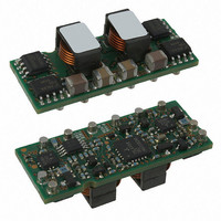
ATS030A0X3-SRPHZ
Manufacturer Part Number
ATS030A0X3-SRPHZ
Description
CONVER DC/DC 0.8 5.5V @ 30A SMD
Manufacturer
Lineage Power
Series
Austin MegaLynx™r
Type
Point of Load (POL) Non-Isolated with Remote On/Offr
Datasheet
1.ATS030A0X3-SRPHZ.pdf
(28 pages)
Specifications of ATS030A0X3-SRPHZ
Output
0.8 ~ 2.75V
Number Of Outputs
1
Power (watts)
165W
Mounting Type
Surface Mount
Voltage - Input
6 ~ 14V
Package / Case
5-SMD Module
1st Output
0.8 ~ 2.75 VDC @ 30A
Size / Dimension
1.30" L x 0.36" W x 0.53" H (33mm x 9.1mm x 13.5mm)
Power (watts) - Rated
165W
Operating Temperature
-40°C ~ 85°C
Efficiency
93%
Approvals
CSA, EN, UL, VDE
Output Power
83 W
Input Voltage Range
6 V to 14 V
Output Voltage (channel 1)
0.8 V to 2.75 V
Output Current (channel 1)
30 A
Package / Case Size
SMD
Output Type
Non-Isolated
Output Voltage
0.8 V to 2.75 V
Product
Non-Isolated / POL
Output Current
30A
Input Voltage
12V
Screening Level
Industrial
Product Length (mm)
33mm
Product Height (mm)
7.53mm
Product Depth (mm)
13.5mm
Mounting Style
Surface Mount
Pin Count
10
Lead Free Status / RoHS Status
Lead free / RoHS Compliant
3rd Output
-
2nd Output
-
Lead Free Status / Rohs Status
Lead free / RoHS Compliant
Other names
555-1152-2
CC109105285
CC109105285
Available stocks
Company
Part Number
Manufacturer
Quantity
Price


Data Sheet
April 9, 2010
Test Configurations
Figure 43. Input Reflected Ripple Current Test
Setup.
Figure 44. Output Ripple and Noise Test Setup.
Figure 45. Output Voltage and Efficiency Test
Setup.
LINEAGE
Efficiency
TO OSCILLOSCOPE
NOTE: All voltage measurements to be taken at the module
NOTE: Measure input reflected ripple current with a simulated
R
R
NOTE: All voltage measurements to be taken at the module
V
COM
distribution
distribution
O
(+)
terminals, as shown above. If sockets are used then
Kelvin connections are required at the module terminals
to avoid measurement errors due to socket contact
resistance.
source inductance (L
possible battery impedance. Measure current as shown
above.
POWER
terminals, as shown above. If sockets are used then
Kelvin connections are required at the module terminals
to avoid measurement errors due to socket contact
resistance.
R
R
contact
contact
η =
@ 20°C 100kHz
E.S.R.<0.1Ω
C
COPPER STRIP
1uF .
S
L
V
1μH
220μF
TEST
IN
V
V
V
COM
IN
IN
O
TEST
(+)
. I
GROUND PLANE
. I
) of 1μH. Capacitor C
O
IN
10uF
COM
V
O
V
150μF
C
x 100 %
O
Min
IN
SCOPE
CURRENT PROBE
Austin MegaLynx
R
R
contact
contact
4.5 – 5.5Vdc input; 0.8 to 3.63Vdc Output; 30A output current
S
offsets
RESISTIVE
LOAD
V
6.0 – 14Vdc Input; 0.8Vdc to 3.63Vdc Output; 20/30A output
COM
IN
(+)
R
R
distribution
distribution
R
LOAD
TM
Design Considerations
The Austin MegaLynx
connected to a low-impedance source. A highly
inductive source can affect the stability of the
module. An input capacitor must be placed directly
adjacent to the input pin of the module, to minimize
input ripple voltage and ensure module stability.
To minimize input voltage ripple, low-ESR ceramic
capacitors are recommended at the input of the
module. Figure 46 shows the input ripple voltage for
various output voltages at 30A of load current with
1x22 µF or 2x22 µF ceramic capacitors and an
input of 12V. Figure 47 shows data for the 5Vin
case, with 2x22µF and 2x47µF of ceramic
capacitors at the input, and for a load current of
30A.
Figure 46. Input ripple voltage for various
output voltages with 1x22 µF or 2x22 µF ceramic
capacitors at the input (30A load). Input voltage
is 12V.
Figure 47. Input ripple voltage in mV, p-p for
various output voltages with 2x22 µF or 2x47 µF
ceramic capacitors at the input (30A load). Input
voltage is 5V.
SMT: Non-Isolated DC-DC Power Modules:
350
300
250
200
150
100
120
100
50
80
60
40
20
0
0
0.5
0.5
1 x 22uF
2 x 22uF
1
Output Voltage (Vdc)
Output Voltage (Vdc)
1
TM
1.5
module should be
1.5
2
2.5
2
2 x 22uF
2 x 47uF
3
14
2.5
3.5
Related parts for ATS030A0X3-SRPHZ
Image
Part Number
Description
Manufacturer
Datasheet
Request
R

Part Number:
Description:
DC/DC Converters & Regulators SMT in 6.0-14Vdc out 0.8-3.63Vdc 30A
Manufacturer:
Lineage Power
Datasheet:
Part Number:
Description:
DC/DC Converters & Regulators SMT in 6.0-14Vdc out 0.8-2.75Vdc 30A
Manufacturer:
Lineage Power
Datasheet:
Part Number:
Description:
DC/DC Converters & Regulators SMT 30A, IN 6-14V OUT 0.8-2.75V
Manufacturer:
Lineage Power
Datasheet:

Part Number:
Description:
DC/DC Converters & Regulators SMT 30A, IN 6-14V OUT 0.8-2.75V
Manufacturer:
Lineage Power
Datasheet:
Part Number:
Description:
DC/DC Converters & Regulators SMT 30A, IN 6-14V OUT 0.8-2.75V
Manufacturer:
Lineage Power
Datasheet:
Part Number:
Description:
Manufacturer:
Lineage Power
Datasheet: