ATS030A0X3-SRPHZ Lineage Power, ATS030A0X3-SRPHZ Datasheet - Page 18
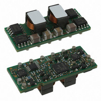
ATS030A0X3-SRPHZ
Manufacturer Part Number
ATS030A0X3-SRPHZ
Description
CONVER DC/DC 0.8 5.5V @ 30A SMD
Manufacturer
Lineage Power
Series
Austin MegaLynx™r
Type
Point of Load (POL) Non-Isolated with Remote On/Offr
Datasheet
1.ATS030A0X3-SRPHZ.pdf
(28 pages)
Specifications of ATS030A0X3-SRPHZ
Output
0.8 ~ 2.75V
Number Of Outputs
1
Power (watts)
165W
Mounting Type
Surface Mount
Voltage - Input
6 ~ 14V
Package / Case
5-SMD Module
1st Output
0.8 ~ 2.75 VDC @ 30A
Size / Dimension
1.30" L x 0.36" W x 0.53" H (33mm x 9.1mm x 13.5mm)
Power (watts) - Rated
165W
Operating Temperature
-40°C ~ 85°C
Efficiency
93%
Approvals
CSA, EN, UL, VDE
Output Power
83 W
Input Voltage Range
6 V to 14 V
Output Voltage (channel 1)
0.8 V to 2.75 V
Output Current (channel 1)
30 A
Package / Case Size
SMD
Output Type
Non-Isolated
Output Voltage
0.8 V to 2.75 V
Product
Non-Isolated / POL
Output Current
30A
Input Voltage
12V
Screening Level
Industrial
Product Length (mm)
33mm
Product Height (mm)
7.53mm
Product Depth (mm)
13.5mm
Mounting Style
Surface Mount
Pin Count
10
Lead Free Status / RoHS Status
Lead free / RoHS Compliant
3rd Output
-
2nd Output
-
Lead Free Status / Rohs Status
Lead free / RoHS Compliant
Other names
555-1152-2
CC109105285
CC109105285
Available stocks
Company
Part Number
Manufacturer
Quantity
Price


Data Sheet
April 9, 2010
feature during start-up is disabled. The pre-bias
immunity feature of the module relies on the module
being in the diode-mode during start-up. When
using the EZ-SEQUENCE
through an internal set-up time of 10msec, and will
be in synchronous rectification mode when voltage
at the SEQ pin is applied. This will result in sinking
current in the module if pre-bias voltage is present
at the output of the module. When pre-bias
immunity during start-up is required, the EZ-
SEQUENCE
Active Load Sharing (-P Option)
For additional power requirements, the Austin
MegaLynx series power module is also available
with a parallel option. Up to five modules can be
configured, in parallel, with active load sharing.
Good layout techniques should be observed when
using multiple units in parallel. To implement forced
load sharing, the following connections should be
made:
•
•
Some special considerations apply for design of
converters in parallel operation:
•
•
LINEAGE
The share pins of all units in parallel must be
connected together. The path of these
connections should be as direct as possible.
All remote-sense pins should be connected to
the power bus at the same point, i.e., connect
all the SENSE
Close proximity and directness are necessary
for good noise immunity
When sizing the number of modules required
for parallel operation, take note of the fact that
current sharing has some tolerance. In
addition, under transient condtions such as a
dynamic load change and during startup, all
converter output currents will not be equal. To
allow for such variation and avoid the likelihood
of a converter shutting off due to a current
overload, the total capacity of the paralleled
system should be no more than 75% of the
sum of the individual converters. As an
example, for a system of four ATS030A0X3-SR
converters the parallel, the total current drawn
should be less that 75% of (4 x 30A) , i.e. less
than 90A.
All modules should be turned on and off
together. This is so that all modules come up at
the same time avoiding the problem of one
converter sourcing current into the other
leading to an overcurrent trip condition. To
ensure that all modules come up
simultaneously, the on/off pins of all paralleled
converters should be tied together and the
POWER
TM
feature must be disabled.
(+)
pins to the
TM
feature, modules goes
(+)
side of the bus.
Austin MegaLynx
4.5 – 5.5Vdc input; 0.8 to 3.63Vdc Output; 30A output current
6.0 – 14Vdc Input; 0.8Vdc to 3.63Vdc Output; 20/30A output
TM
•
SMT: Non-Isolated DC-DC Power Modules:
converters enabled and disabled using the
on/off pin.
The share bus is not designed for redundant
operation and the system will be non-functional
upon failure of one of the unit when multiple
units are in parallel. In particular, if one of the
converters shuts down during operation, the
other converters may also shut down due to
their outputs hitting current limit. In such a
situation, unless a coordinated restart is
ensured, the system may never properly restart
since different converters will try to restart at
different times causing an overload condition
and subsequent shutdown. This situation can
be avoided by having an external output
voltage monitor circuit that detects a shutdown
condition and forces all converters to shut
down and restart together.
18
Related parts for ATS030A0X3-SRPHZ
Image
Part Number
Description
Manufacturer
Datasheet
Request
R

Part Number:
Description:
DC/DC Converters & Regulators SMT in 6.0-14Vdc out 0.8-3.63Vdc 30A
Manufacturer:
Lineage Power
Datasheet:
Part Number:
Description:
DC/DC Converters & Regulators SMT in 6.0-14Vdc out 0.8-2.75Vdc 30A
Manufacturer:
Lineage Power
Datasheet:
Part Number:
Description:
DC/DC Converters & Regulators SMT 30A, IN 6-14V OUT 0.8-2.75V
Manufacturer:
Lineage Power
Datasheet:

Part Number:
Description:
DC/DC Converters & Regulators SMT 30A, IN 6-14V OUT 0.8-2.75V
Manufacturer:
Lineage Power
Datasheet:
Part Number:
Description:
DC/DC Converters & Regulators SMT 30A, IN 6-14V OUT 0.8-2.75V
Manufacturer:
Lineage Power
Datasheet:
Part Number:
Description:
Manufacturer:
Lineage Power
Datasheet: