LSM2-T/30-D12R-C Murata Power Solutions Inc, LSM2-T/30-D12R-C Datasheet - Page 5
LSM2-T/30-D12R-C
Manufacturer Part Number
LSM2-T/30-D12R-C
Description
CONV DC/DC 125W 30A 12V SMD
Manufacturer
Murata Power Solutions Inc
Series
LSM2r
Type
Point of Load (POL) Non-Isolatedr
Datasheet
1.LSM2-T30-D12-C.pdf
(11 pages)
Specifications of LSM2-T/30-D12R-C
Output
0.8 ~ 5V
Number Of Outputs
1
Power (watts)
125W
Mounting Type
Surface Mount
Voltage - Input
8.3 ~ 13.2V
Package / Case
8-DIP SMD Module
1st Output
0.8 ~ 5 VDC @ 30A
Size / Dimension
1.30" L x 0.53" W x 0.34" H (33mm x 13.5mm x 8.6mm)
Power (watts) - Rated
125W
Operating Temperature
-40°C ~ 85°C
Efficiency
94%
Approvals
CSA, cUL, EN, UL
Output Power
150 W
Input Voltage Range
6 V to 14 V
Output Voltage (channel 1)
0.8 V to 5 V
Output Current (channel 1)
30 A
Product
Non-Isolated / POL
Input Voltage (nominal)
12 V
Package / Case Size
SMD
Output Type
Non-Isolated POL
Output Voltage
0.8 V to 5 V
Lead Free Status / RoHS Status
Lead free / RoHS Compliant
3rd Output
-
2nd Output
-
Lead Free Status / Rohs Status
Lead free / RoHS Compliant
Other names
811-1793
811-1793-1
811-1793-1
811-1793-1
811-1793-1
Available stocks
Company
Part Number
Manufacturer
Quantity
Price
Company:

Part Number:
LSM2-T/30-D12R-C
Manufacturer:
TI/NSC
Quantity:
9 400


(7) If Sense is connected remotely at the load, up to 0.5 Volts difference is allowed between the
(8) Output noise may be further reduced by adding an external fi lter. See I/O Filtering and Noise Reduc-
(9) All models are fully operational and meet published specifi cations, including “cold start” at –40° C.
(10) Regulation specifi cations describe the deviation as the line input voltage or output load current
(11) Other input or output voltage ranges will be reviewed under scheduled quantity special order.
(12) Maximum continuous power requires that all on-board components not exceed +128°C pack-
(13) Do not exceed maximum power specifi cations when adjusting the output trim.
(14) The “R” option includes extra ground pads. These pads offer two important features. In addition
(15) The maximum output capacitive loads depend on the the Equivalent Series Resistance (ESR)
(16) Do not use Pre-bias startup and sequencing together. If you do not use the track function, leave
(17) After short circuit shutdown, if the load is partially removed such that the load still exceeds the
(18) Output current limiting is disabled at start up to avoid overcurrent shutdown while charging
The LSM2-T/30-D12 series includes a special output voltage trimming fea-
ture which is fully compatible with competitive units. The output voltage may
be varied using a single trim resistor from the Trim Input to Power Common.
the converter with short leads. Be aware that the voltage accuracy is ±1.5%
(typical) therefore adjust this resistance to achieve your desired output.
Murata Power Solutions recommends the specifi cations below when installing these converters. These specifi cations vary depending on the solder type. Exceeding these specifi ca-
tions may cause damage to the product. Your production environment may differ therefore please thoroughly review these guidelines with your process engineers.
Preheat Temperature
Time over Liquidus
Maximum Peak Temperature
Cooling Rate
Use a precision, low-tempco resistor (±100 ppm/
Sense and +V
age drop may cause the converter to exceed maximum power dissipation.
tion.
is varied from a nominal midpoint value to either extreme.
age temperature.
to carrying extra current, they also help dissipate additional heat. MPS strongly recommends
soldering the “R” pads to a thick ground plane with sizable area. The Operating Temperature
specifi cation listed above assumes that these additional ground pads are connected to
a substantial ground plane below the converter ( at least several square inches).
of the external output capacitor. Larger caps will reduce output noise but may slow transient
response.
the seq/trk pin open.
overcurrent (OC) detection, the converter will remain in hiccup restart mode.
external bypass capacitors.
OUT
pins to compensate for ohmic voltage drop in the power lines. A larger volt-
Less than 1 ºC. per second
45 to 75 seconds
260 ºC.
Less than 3 ºC. per second
ο
C) mounted close to
Preheat Temperature
Time over Liquidus
Maximum Peak Temperature
Cooling Rate
www.murata-ps.com
Less than 1 ºC. per second
60 to 75 seconds
235 ºC.
Less than 3 ºC. per second
The fi xed trim resistors to set the output voltage are:
The LSM2 Series may also be trimmed using an external low-noise voltage
applied between the Trim input and Output Common. Be aware that the inter-
nal “load” impedance looking into Trim pin is below 1000 Ohms and includes
factors from the output voltage. Therefore, use a low impedance source
resistance in your external voltage reference.
The fi xed trim voltages to set the output voltage are:
Vtrim = 0.7434 – [(((Vout – 0.7434) ÷ 1620) – 0.000035) x 100] where Vout
= desired voltage
V
Rtrim (Ohms)
V
Rtrim (Ohms)
V
Vtrim (Volts)
V
Vtrim (Volts)
OUT
OUT
OUT
OUT
(typ.)
(typ.)
R
TRIM
0.90 KΩ
0.669V.
0.80V.
(in Ohms) =
Open
Open
2.0 V.
0.8V.
2.0V.
DOSA-SMT, 30A POL DC/DC Converters
5.90 KΩ
0.731V.
0.638V.
605 Ω
1.0V.
2.5V.
1.0V.
2.5V.
---------------------
V
OUT
2.90 KΩ
1200
0.719V.
0.589V.
380 Ω
1.2V.
3.3V.
1.2V.
3.3V.
– 0.8
Voltage Reference,
0.484V.
185.71
1.614
1.5V.
5.0V.
1.5V.
0.7V.
5.0V.
-100
KΩ
Ω
Page 5 of 11
1.10 KΩ
0.682V
1.8V.
1.8V.
Related parts for LSM2-T/30-D12R-C
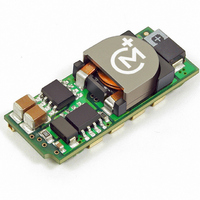
Image
Part Number
Description
Manufacturer
Datasheet
Request
R

Part Number:
Description:
CONV DC/DC 125W 30A 12V SMD
Manufacturer:
Murata Power Solutions Inc
Datasheet:

Part Number:
Description:
CONV DC/DC 30W 6A 12V SMD
Manufacturer:
Murata Power Solutions Inc
Datasheet:
Part Number:
Description:
CONV DC/DC 30W 6A 12V SMD
Manufacturer:
Murata Power Solutions Inc
Datasheet:

Part Number:
Description:
DC/DC Converter
Manufacturer:
Murata Power Solutions Inc
Datasheet:
Part Number:
Description:
DC/DC Converter
Manufacturer:
Murata Power Solutions Inc
Datasheet:
Part Number:
Description:
CONV DC/DC 19.8W 6A 5V SMD
Manufacturer:
Murata Power Solutions Inc
Datasheet:
Part Number:
Description:
CONV DC/DC 19.8W 6A 5V SMD
Manufacturer:
Murata Power Solutions Inc
Datasheet:
Part Number:
Description:
CONV DC/DC 33W 10A 5V SMD
Manufacturer:
Murata Power Solutions Inc
Datasheet:
Part Number:
Description:
CONV DC/DC 33W 10A 5V SMD
Manufacturer:
Murata Power Solutions Inc
Datasheet:
Part Number:
Description:
CONV DC/DC 50W 10A 12V SMD
Manufacturer:
Murata Power Solutions Inc
Datasheet:

Part Number:
Description:
DC/DC Converter
Manufacturer:
Murata Power Solutions Inc
Datasheet:

Part Number:
Description:
Transformers 5Vin 5Vout 200mA 4000Vdc 1:1.33 turn
Manufacturer:
Murata Power Solutions Inc
Datasheet:

Part Number:
Description:
POWER SUPPLY
Manufacturer:
Murata Power Solutions Inc
Datasheet:

Part Number:
Description:
DPM LED MINI 2VDC 3.5DIG LP RED
Manufacturer:
Murata Power Solutions Inc
Datasheet:

Part Number:
Description:
CONV DC/DC 1W 5VIN 5VOUT SIP SGL
Manufacturer:
Murata Power Solutions Inc
Datasheet: