AC164112 Microchip Technology, AC164112 Datasheet - Page 152
AC164112
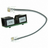
Manufacturer Part Number
AC164112
Description
VOLTAGE LIMITER MPLAB ICD2 VPP
Manufacturer
Microchip Technology
Datasheet
1.AC164112.pdf
(302 pages)
Specifications of AC164112
Accessory Type
Voltage Limiter
Product
Cable Assemblies
Features
Programming And Debugging The Latest PIC12/PIC16/PIC18 Products
Development Tool Type
Hardware - Eval/Demo Board
Lead Free Status / RoHS Status
Lead free / RoHS Compliant
For Use With/related Products
MPLAB®
Lead Free Status / Rohs Status
Lead free / RoHS Compliant
For Use With
MPLAB ICD 2
Lead Free Status / RoHS Status
Lead free / RoHS Compliant, Lead free / RoHS Compliant
Available stocks
Company
Part Number
Manufacturer
Quantity
Price
Company:

Part Number:
AC164112
Manufacturer:
Microchip Technology
Quantity:
135


PIC16F72X/PIC16LF72X
16.1.2.8
1.
2.
3.
4.
5.
6.
7.
8.
9.
FIGURE 16-5:
DS41341E-page 152
Initialize the SPBRG register and the BRGH bit
to achieve the desired baud rate (refer to
Section 16.2 “AUSART Baud Rate Generator
(BRG)”).
Enable the serial port by setting the SPEN bit.
The SYNC bit must be clear for asynchronous
operation.
If interrupts are desired, set the RCIE bit of the
PIE1 register and the GIE and PEIE bits of the
INTCON register.
If 9-bit reception is desired, set the RX9 bit.
Enable reception by setting the CREN bit.
The RCIF interrupt flag bit of the PIR1 register
will be set when a character is transferred from
the RSR to the receive buffer. An interrupt will be
generated if the RCIE bit of the PIE1 register
was also set.
Read the RCSTA register to get the error flags
and, if 9-bit data reception is enabled, the ninth
data bit.
Get the received 8 Least Significant data bits
from the receive buffer by reading the RCREG
register.
If an overrun occurred, clear the OERR flag by
clearing the CREN receiver enable bit.
Note:
RX/DT pin
Rcv Shift
Reg
Rcv Buffer Reg
Read Rcv
Buffer Reg
RCREG
RCIF
(Interrupt Flag)
OERR bit
CREN
Asynchronous Reception Set-up:
This timing diagram shows three words appearing on the RX input. The RCREG (receive buffer) is read after the third word,
causing the OERR (overrun) bit to be set.
Start
ASYNCHRONOUS RECEPTION
bit
bit 0
bit 1
bit 7/8
Stop
bit
Word 1
RCREG
Start
bit
bit 0
16.1.2.9
This mode would typically be used in RS-485 systems.
To set up an Asynchronous Reception with Address
Detect Enable:
1.
2.
3.
4.
5.
6.
7.
8.
9.
10. If an overrun occurred, clear the OERR flag by
11. If the device has been addressed, clear the
Initialize the SPBRG register and the BRGH bit
to achieve the desired baud rate (refer to
Section 16.2 “AUSART Baud Rate Generator
(BRG)”).
Enable the serial port by setting the SPEN bit.
The SYNC bit must be clear for asynchronous
operation.
If interrupts are desired, set the RCIE bit of the
PIE1 register and the GIE and PEIE bits of the
INTCON register.
Enable 9-bit reception by setting the RX9 bit.
Enable address detection by setting the ADDEN
bit.
Enable reception by setting the CREN bit.
The RCIF interrupt flag bit of the PIR1 register
will be set when a character with the ninth bit set
is transferred from the RSR to the receive buffer.
An interrupt will be generated if the RCIE inter-
rupt enable bit of the PIE1 register was also set.
Read the RCSTA register to get the error flags.
The ninth data bit will always be set.
Get the received 8 Least Significant data bits
from the receive buffer by reading the RCREG
register. Software determines if this is the
device’s address.
clearing the CREN receiver enable bit.
ADDEN bit to allow all received data into the
receive buffer and generate interrupts.
bit 7/8 Stop
Word 2
RCREG
9-bit Address Detection Mode Set-up
bit
Start
© 2009 Microchip Technology Inc.
bit
bit 7/8
Stop
bit
Related parts for AC164112
Image
Part Number
Description
Manufacturer
Datasheet
Request
R

Part Number:
Description:
Manufacturer:
Microchip Technology Inc.
Datasheet:
Part Number:
Description:
Manufacturer:
Microchip Technology Inc.
Datasheet:
Part Number:
Description:
Manufacturer:
Microchip Technology Inc.
Datasheet:
Part Number:
Description:
Manufacturer:
Microchip Technology Inc.
Datasheet:
Part Number:
Description:
Manufacturer:
Microchip Technology Inc.
Datasheet:
Part Number:
Description:
Manufacturer:
Microchip Technology Inc.
Datasheet:
Part Number:
Description:
Manufacturer:
Microchip Technology Inc.
Datasheet:
Part Number:
Description:
Manufacturer:
Microchip Technology Inc.
Datasheet: