AC164112 Microchip Technology, AC164112 Datasheet - Page 46
AC164112
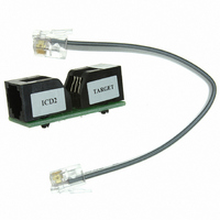
Manufacturer Part Number
AC164112
Description
VOLTAGE LIMITER MPLAB ICD2 VPP
Manufacturer
Microchip Technology
Datasheet
1.AC164112.pdf
(302 pages)
Specifications of AC164112
Accessory Type
Voltage Limiter
Product
Cable Assemblies
Features
Programming And Debugging The Latest PIC12/PIC16/PIC18 Products
Development Tool Type
Hardware - Eval/Demo Board
Lead Free Status / RoHS Status
Lead free / RoHS Compliant
For Use With/related Products
MPLAB®
Lead Free Status / Rohs Status
Lead free / RoHS Compliant
For Use With
MPLAB ICD 2
Lead Free Status / RoHS Status
Lead free / RoHS Compliant, Lead free / RoHS Compliant
Available stocks
Company
Part Number
Manufacturer
Quantity
Price
Company:

Part Number:
AC164112
Manufacturer:
Microchip Technology
Quantity:
135


PIC16F72X/PIC16LF72X
4.5.1
The INTCON register is a readable and writable
register, which contains the various enable and flag bits
for TMR0 register overflow, PORTB change and
external RB0/INT/SEG0 pin interrupts.
REGISTER 4-1:
DS41341E-page 46
bit 7
Legend:
R = Readable bit
-n = Value at POR
bit 7
bit 6
bit 5
bit 4
bit 3
bit 2
bit 1
bit 0
Note 1:
R/W-0
GIE
2:
The appropriate bits in the IOCB register must also be set.
T0IF bit is set when Timer0 rolls over. Timer0 is unchanged on Reset and should be initialized before
clearing T0IF bit.
INTCON REGISTER
GIE: Global Interrupt Enable bit
1 = Enables all unmasked interrupts
0 = Disables all interrupts
PEIE: Peripheral Interrupt Enable bit
1 = Enables all unmasked peripheral interrupts
0 = Disables all peripheral interrupts
T0IE: Timer0 Overflow Interrupt Enable bit
1 = Enables the Timer0 interrupt
0 = Disables the Timer0 interrupt
INTE: RB0/INT External Interrupt Enable bit
1 = Enables the RB0/INT external interrupt
0 = Disables the RB0/INT external interrupt
RBIE: PORTB Change Interrupt Enable bit
1 = Enables the PORTB change interrupt
0 = Disables the PORTB change interrupt
T0IF: Timer0 Overflow Interrupt Flag bit
1 = TMR0 register has overflowed (must be cleared in software)
0 = TMR0 register did not overflow
INTF: RB0/INT External Interrupt Flag bit
1 = The RB0/INT external interrupt occurred (must be cleared in software)
0 = The RB0/INT external interrupt did not occur
RBIF: PORTB Change Interrupt Flag bit
1 = When at least one of the PORTB general purpose I/O pins changed state (must be cleared in soft-
0 = None of the PORTB general purpose I/O pins have changed state
R/W-0
PEIE
ware)
INTCON: INTERRUPT CONTROL REGISTER
W = Writable bit
‘1’ = Bit is set
R/W-0
T0IE
R/W-0
INTE
(2)
(1)
U = Unimplemented bit, read as ‘0’
‘0’ = Bit is cleared
RBIE
R/W-0
Note:
(1)
Interrupt flag bits are set when an interrupt
condition occurs, regardless of the state of
its corresponding enable bit or the global
enable bit, GIE of the INTCON register.
User software should ensure the appropri-
ate interrupt flag bits are clear prior to
enabling an interrupt.
T0IF
R/W-0
(2)
© 2009 Microchip Technology Inc.
x = Bit is unknown
R/W-0
INTF
R/W-x
RBIF
bit 0
Related parts for AC164112
Image
Part Number
Description
Manufacturer
Datasheet
Request
R

Part Number:
Description:
Manufacturer:
Microchip Technology Inc.
Datasheet:
Part Number:
Description:
Manufacturer:
Microchip Technology Inc.
Datasheet:
Part Number:
Description:
Manufacturer:
Microchip Technology Inc.
Datasheet:
Part Number:
Description:
Manufacturer:
Microchip Technology Inc.
Datasheet:
Part Number:
Description:
Manufacturer:
Microchip Technology Inc.
Datasheet:
Part Number:
Description:
Manufacturer:
Microchip Technology Inc.
Datasheet:
Part Number:
Description:
Manufacturer:
Microchip Technology Inc.
Datasheet:
Part Number:
Description:
Manufacturer:
Microchip Technology Inc.
Datasheet: