MA180021 Microchip Technology, MA180021 Datasheet - Page 11
MA180021
Manufacturer Part Number
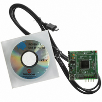
MA180021
Description
MODULE PLUG-IN 18F87J50 FS USB
Manufacturer
Microchip Technology
Series
PIC®r
Specifications of MA180021
Accessory Type
Plug-In Module (PIM) - PIC18F87J50
Silicon Manufacturer
Microchip
Core Architecture
PIC
Core Sub-architecture
PIC18
Features
Full Speed USB Demonstration, Operated Either Stand Alone Or As Plug-In Module
Silicon Core Number
PIC18F
Silicon Family Name
PIC18FxxJxx
Lead Free Status / RoHS Status
Lead free / RoHS Compliant
For Use With/related Products
HPC Explorer Board (DM183022) or PIC18 Explorer Board (DM183032)
For Use With
DM183032 - BOARD EXPLORER PICDEM PIC18DM183022 - BOARD DEMO PIC18FXX22 64/80TQFP
Lead Free Status / RoHS Status
Lead free / RoHS Compliant
Available stocks
Company
Part Number
Manufacturer
Quantity
Price
Company:

Part Number:
MA180021
Manufacturer:
Microchip Technology
Quantity:
135


2.1
2.2
© 2007 Microchip Technology Inc.
HIGHLIGHTS
USING THE PIM WITH THE HPC EXPLORER BOARD
Chapter 2. Important Notes and Migration Tips
This chapter discusses:
• Using the PIM with the HPC Explorer Board
• Programming the Microcontroller
• Migrating to the PIC18F87J50 Family
If the PIM will be used with the HPC Explorer board, be sure to set switch, S3, on the
HPC Explorer to the “ICE” position PRIOR TO INSTALLING THE PIM. When the
switch is in the ICE position, the MCLR line on the PIC18F8722 microcontroller, located
on the HPC Explorer, will be held low. Additionally, V
PIC18F8722. This is intended to prevent simultaneous code execution on both the
microcontroller located on the HPC Explorer board and on the PIM. Almost all of the
I/O pins on the PIM are directly connected to the same I/O pins on the PIC18F8722 of
the HPC Explorer board. For example, when the two boards are connected together,
microcontroller pin, RD0 on the PIC18F87J50 FS USB PIM, is directly connected to the
RD0 pin on the PIC18F8722, as well as one of the green LEDs on the HPC Explorer
board.
If both microcontrollers could execute code simultaneously, I/O pins configured as out-
puts could easily result in I/O pin contention and possible device damage. To prevent
this potential condition, the S3 switch on the HPC Explorer board should always be in
the “ICE” position when a PIM is installed.
The “P4” pin on the PIC18F87J50 FS USB Plug-In Module is intended to physically
interfere with switch, S3, on the HPC Explorer board. If the switch is not in the correct
position, the PIM will not sit fully seated. To avoid physically damaging the PIM or the
HPC Explorer board, never use excessive force when installing the PIM, and always
check that switch S3 on the HPC Explorer board is in the correct position.
The PIC18F87J50 FS USB PIM has been specifically designed to work either
stand-alone or while plugged into the HPC Explorer board, revision 5. HPC Explorer
revision 4 boards will also work, although capacitor, C3, may be too tall to allow the PIM
to sit fully seated. The interference should not be enough to prevent electrical con-
nectivity, but if it does, it is recommended to replace C3 with a physically smaller
capacitor. The HPC Explorer revision number can be found etched in the copper on the
bottom side of the PCB just underneath the 9-pin serial port connector.
PIC18F87J50 FS USB
PLUG-IN MODULE
DD
will not be connected to the
USER’S GUIDE
DS51678A-page 7
Related parts for MA180021
Image
Part Number
Description
Manufacturer
Datasheet
Request
R

Part Number:
Description:
Manufacturer:
Microchip Technology Inc.
Datasheet:
Part Number:
Description:
Manufacturer:
Microchip Technology Inc.
Datasheet:
Part Number:
Description:
Manufacturer:
Microchip Technology Inc.
Datasheet:
Part Number:
Description:
Manufacturer:
Microchip Technology Inc.
Datasheet:
Part Number:
Description:
Manufacturer:
Microchip Technology Inc.
Datasheet:
Part Number:
Description:
Manufacturer:
Microchip Technology Inc.
Datasheet:
Part Number:
Description:
Manufacturer:
Microchip Technology Inc.
Datasheet:
Part Number:
Description:
Manufacturer:
Microchip Technology Inc.
Datasheet: