MA180021 Microchip Technology, MA180021 Datasheet - Page 13
MA180021
Manufacturer Part Number
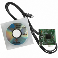
MA180021
Description
MODULE PLUG-IN 18F87J50 FS USB
Manufacturer
Microchip Technology
Series
PIC®r
Specifications of MA180021
Accessory Type
Plug-In Module (PIM) - PIC18F87J50
Silicon Manufacturer
Microchip
Core Architecture
PIC
Core Sub-architecture
PIC18
Features
Full Speed USB Demonstration, Operated Either Stand Alone Or As Plug-In Module
Silicon Core Number
PIC18F
Silicon Family Name
PIC18FxxJxx
Lead Free Status / RoHS Status
Lead free / RoHS Compliant
For Use With/related Products
HPC Explorer Board (DM183022) or PIC18 Explorer Board (DM183032)
For Use With
DM183032 - BOARD EXPLORER PICDEM PIC18DM183022 - BOARD DEMO PIC18FXX22 64/80TQFP
Lead Free Status / RoHS Status
Lead free / RoHS Compliant
Available stocks
Company
Part Number
Manufacturer
Quantity
Price
Company:

Part Number:
MA180021
Manufacturer:
Microchip Technology
Quantity:
135


© 2007 Microchip Technology Inc.
2.4.2
The PIC18F87J50 family devices use the same 96 MHz PLL found in prior full-speed
USB microcontrollers, such as the PIC18F4550, but the implementation of the surround-
ing clock structure is slightly different. When migrating up to the PIC18F87J50 family of
devices, the most important change is the PLL does not automatically start when the
microcontroller is powered on, even if it is programmed to use one of the PLL-enabled
modes (e.g., HS+PLL). This allows the microcontroller to start up at less than the
maximum operating frequency. This can potentially be advantageous when running from
a decaying power source (such as a battery), where the applied voltage may not be
adequate for maximum frequency operation. For applications such as these, the
WDTCON<LVDSTAT> bit can be polled to determine if firmware can safely switch to
maximum frequency operation.
After the Power-up Timer expires and the microcontroller begins code execution, the
OSCTUNE<PLLEN> bit must be set by user firmware to activate the PLL (in
PLL-enabled modes). The PLL requires up to 2 ms to lock, during which time, the
microcontroller continues to execute code at the PLL-disabled frequency. User firm-
ware should not attempt to enable the USB module by setting the UCON<USBEN> bit
until after the PLL has locked (unless the PLL is not being used to derive the USB
module clock).
2.4.3
The PIC18F87J50 family of microcontrollers offers more flexibility compared to
previous PIC18 devices when selecting which I/O pins should use analog input buffers,
and which ones should use digital input buffers. Previous PIC18 microcontrollers used
the ADCON1 register to control this function, but the PIC18F87J50 family devices use
two new registers, ANCON0 and ANCON1, for this purpose. These new registers allow
the PIC18F87J50 family of microcontrollers to individually and independently select
which ANx pins should use digital or analog input buffers. See the Analog-to-Digital
converter chapter in the device data sheet for more details.
Oscillator Configuration
Input Buffer Selection
Important Notes and Migration Tips
DS51678A-page 9
Related parts for MA180021
Image
Part Number
Description
Manufacturer
Datasheet
Request
R

Part Number:
Description:
Manufacturer:
Microchip Technology Inc.
Datasheet:
Part Number:
Description:
Manufacturer:
Microchip Technology Inc.
Datasheet:
Part Number:
Description:
Manufacturer:
Microchip Technology Inc.
Datasheet:
Part Number:
Description:
Manufacturer:
Microchip Technology Inc.
Datasheet:
Part Number:
Description:
Manufacturer:
Microchip Technology Inc.
Datasheet:
Part Number:
Description:
Manufacturer:
Microchip Technology Inc.
Datasheet:
Part Number:
Description:
Manufacturer:
Microchip Technology Inc.
Datasheet:
Part Number:
Description:
Manufacturer:
Microchip Technology Inc.
Datasheet: