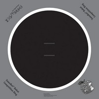
27404 Parallax Inc, 27404 Datasheet - Page 102

27404
Manufacturer Part Number
27404
Description
COMPETITION RING FOR SUMOBOT
Manufacturer
Parallax Inc
Datasheet
1.27404.pdf
(266 pages)
Specifications of 27404
Accessory Type
Hobby and Education
Product
Microcontroller Accessories
Lead Free Status / RoHS Status
Contains lead / RoHS non-compliant
For Use With/related Products
SumoBot®
Lead Free Status / RoHS Status
Lead free / RoHS Compliant, Contains lead / RoHS non-compliant
- Current page: 102 of 266
- Download datasheet (6Mb)
uses
named
Remember that P10 has to be set high to turn on the QTI, and low to turn it back off
again when the measurement is done. With the use of
a name, the code should look about like this:
The rate at which the voltage decays is shown in Figure 3-11. When the QTI is over the
white tawara line that surrounds the sumo ring surface, lots of reflected IR makes it to the
IR transistor's base. In this situation, the IR transistor will conduct more current, and V
will drop very quickly. A typical
anywhere between 15 and 350 depending on the surface and the ambient light in the
room. When the QTI is placed over the black sumo ring, the value might be 1500. That's
because the black surface absorbs infrared, and not nearly as much makes it to the base of
the IR transistor. With less IR striking its base, the transistor conducts less current, and
V
0
decays much more slowly.
RCTIME
temp
HIGH 9
PAUSE 1
RCTIME 9, 1, temp
qtiPwrLeft
qtiSigLeft
qtiLeft
HIGH qtiPwrLeft
HIGH qtiSigLeft
PAUSE 1
RCTIME qtiSigLeft, 1, temp
LOW qtiPwrLeft
DEBUG CRSRX, 0, DEC5 qtiLeft
:
to measure and store the time it took for V
PIN
PIN
VAR
10
9
Word
RCTIME
value for this is 85, though it could range
PIN
' Left QTI on/off pin
' Left QTI signal pin
' Stores left QTI time
' Turn left QTI on
' Discharge capacitor
' Measure charge time
' Turn left QTI off
' Display time measurement
0
to decay to 1.4 V in a variable
directives to give each I/O pin
0
Related parts for 27404
Image
Part Number
Description
Manufacturer
Datasheet
Request
R

Part Number:
Description:
Microcontroller Modules & Accessories DISCONTINUED BY PARALLAX
Manufacturer:
Parallax Inc

Part Number:
Description:
BOOK UNDERSTANDING SIGNALS
Manufacturer:
Parallax Inc
Datasheet:

Part Number:
Description:
TEXT INFRARED REMOTE FOR BOE-BOT
Manufacturer:
Parallax Inc
Datasheet:

Part Number:
Description:
BOARD EXPERIMENT+LCD NX-1000
Manufacturer:
Parallax Inc
Datasheet:

Part Number:
Description:
CONTROLLER 16SERVO MOTOR CONTROL
Manufacturer:
Parallax Inc
Datasheet:

Part Number:
Description:
BASIC STAMP LOGIC ANALYZER
Manufacturer:
Parallax Inc
Datasheet:

Part Number:
Description:
IC MCU 2K FLASH 50MHZ SO-18
Manufacturer:
Parallax Inc
Datasheet:

Part Number:
Description:
IC MCU 2K FLASH 50MHZ 28SSOP
Manufacturer:
Parallax Inc
Datasheet:


