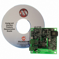
MCP1630RD-DDBK3 Microchip Technology, MCP1630RD-DDBK3 Datasheet - Page 12

MCP1630RD-DDBK3
Manufacturer Part Number
MCP1630RD-DDBK3
Description
REF DESIGN MCP1630V BI-DIR 4CELL
Manufacturer
Microchip Technology
Type
Battery Managementr
Specifications of MCP1630RD-DDBK3
Main Purpose
Power Management, Battery Charger
Embedded
Yes, MCU, 8-Bit
Utilized Ic / Part
MCP1630
Primary Attributes
4 Cells- Li-Ion, 6.5 ~ 7 V Input
Secondary Attributes
MCU Generates Frequency, 94% Efficiency, 2 Status LEDs
Input Voltage
6.5 V to 7 V
Product
Power Management Modules
For Use With/related Products
MCP1630V, PIC16F88, MCP6022
Lead Free Status / RoHS Status
Not applicable / Not applicable
Lead Free Status / RoHS Status
Lead free / RoHS Compliant, Not applicable / Not applicable
MCP1630V Bidirectional 4 Cell Li-Ion Charger Reference Design User’s Guide
2.6
DS51641A-page 8
GETTING STARTED
The MCP1630V Bidirectional 4 Cell Li-Ion Charger Reference Design is fully
assembled and tested for charging a four series cell Li-Ion battery pack (Battery Pack
should have internal overvoltage, overcurrent and overtemperature protection). The
board requires the use of an external input voltage source (+7.0V) for charging.
2.6.1
2.6.1.1
1. Connect the positive side of the +6.5V to +7.0V input to J2 Pin 2, connect the
2. Connect the positive side of the Four cell Li-Ion battery pack voltage to J1 Pin 1,
3. Once the SW1 push button is pressed, the MCP1630V Bidirectional 4 Cell Li-Ion
4. LED D3 will be illuminated when the board is running, (charging or bucking).
5. LED D5 will flash only when a charge cycle is in progress.
6. Again, a subsequent pressing of the SW1 push button during normal operation
FIGURE 2-2:
I
Note:
+14 V
negative side (or ground) to Pin 1 of J2. This source voltage should not exceed
7.0 and be rated for 8A minimum supply current.
connect the battery pack return to the negative side of J1 Pin 2.
Charger Reference Design is powered. When powered, a charge cycle will start
automatically if the 7.0V is connected and all preconditions are meet, (see
Appendix C. “Firmware”).
of the MCP1630V Bidirectional 4 Cell Li-Ion Charger Reference Design will
power-off the converter.
+7V
BAT
Power Input and Output Connection
POWERING THE MCP1630V BIDIRECTIONAL 4 CELL LI-ION
CHARGER REFERENCE DESIGN
Both supplies should have a separate isolated return (ground), there is a
current sense resistor between the +7.0V (V
returns. If the returns are connected, the charge current can not be
controlled.
Board Top Assembly and Connections
LOCATIONS
D3
FOR
D5
BULK
© 2006 Microchip Technology Inc.
) and +14V(V
BATT
SW1
SWITCH
CONN
ICD 2
) supply


