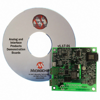
MCP1630RD-DDBK3 Microchip Technology, MCP1630RD-DDBK3 Datasheet - Page 13

MCP1630RD-DDBK3
Manufacturer Part Number
MCP1630RD-DDBK3
Description
REF DESIGN MCP1630V BI-DIR 4CELL
Manufacturer
Microchip Technology
Type
Battery Managementr
Specifications of MCP1630RD-DDBK3
Main Purpose
Power Management, Battery Charger
Embedded
Yes, MCU, 8-Bit
Utilized Ic / Part
MCP1630
Primary Attributes
4 Cells- Li-Ion, 6.5 ~ 7 V Input
Secondary Attributes
MCU Generates Frequency, 94% Efficiency, 2 Status LEDs
Input Voltage
6.5 V to 7 V
Product
Power Management Modules
For Use With/related Products
MCP1630V, PIC16F88, MCP6022
Lead Free Status / RoHS Status
Not applicable / Not applicable
Lead Free Status / RoHS Status
Lead free / RoHS Compliant, Not applicable / Not applicable
© 2006 Microchip Technology Inc.
2.6.1.2
A four cell battery pack (with internal protection) is connected to the J1 connector
before applying input power and pressing SW1 to start the charge cycle. Once the
battery pack is connected, SW1 can be pressed to start the synchronous buck
converter (assuming there is no 7.0V input applied to J2). With the battery pack
connected, the source for J2 can be “hot” plugged in and out, a voltage will always be
present on J2 until SW1 is pressed shutting off the converter.
2.6.1.3
As an alternative to the four cell Li-Ion battery pack, a battery pack simulation circuit
can be used,
power load resistor (10Ω, 100W), Aluminum Electrolytic Capacitor (3,300 µF 25V) and
Schottky Diode (10V, 30V). For evaluating the bidirectional converter design, the bat-
tery simulator circuit is recommended. When using the battery pack simulator, the
operating point for charging and discharging can be easily be adjusted using the V
power supply and load resistor value.
2.6.1.4
Two LED’s are connected to the I/O of the PIC16F88 to provide status of the charger.
LED D3 provides indication that the converter is running while LED D5 flashing
provides indication that the converter is charging. With a 6.5V to 7.0V source applied
to J2 while the converter is running, a charge cycle is initiated. Once the charge cycle
is complete, the charger will continue to operate providing 0 mA of current to the
battery. If the source is removed from J2, the converter will regulate the V
to 6.0V with a load up to 6A.
Evaluating the Application
The best way to evaluate the MCP1630V Bidirectional 4 Cell Li-Ion Charger Reference
Design is to operate the bidirectional power system over a wide range using the battery
pack simulator. The simulator consists of a 10
voltage source. When configured as shown in
battery. The load resistor is used to sink current from the charger while a large capacitor
is used to simulate the battery voltage (V
operating points in the charge cycle can be evaluated.
Once evaluated using the battery pack simulator, the bi-directional reference design
can be used to run charge and discharge cycles using a four cell Li-ion battery pack. If
using an actual Li-ion battery pack, it must have the proper protection features
including, (overvoltage, overcurrent, overtemperature, etc.).
APPLYING BATTERY TO MCP1630V BIDIRECTIONAL 4 CELL LI-ION
CHARGER REFERENCE DESIGN
ALTERNATIVE BATTERY PACK SIMULATOR
LED STATUS INDICATION
(Figure
2-3). This simulation circuit consists of an adjustable metal wound
SIM
). By adjusting the V
Ω
Figure
power resistor, diode and variable
2-3, the circuit will simulate a
SIM
voltage, different
DS51641A-page 9
BULK
voltage
BATT


