EVAL-AD9833EBZ Analog Devices Inc, EVAL-AD9833EBZ Datasheet - Page 22
EVAL-AD9833EBZ
Manufacturer Part Number
EVAL-AD9833EBZ
Description
BOARD EVAL FOR AD9833
Manufacturer
Analog Devices Inc
Datasheet
1.AD9833BRMZ.pdf
(24 pages)
Specifications of EVAL-AD9833EBZ
Main Purpose
Timing, Direct Digital Synthesis (DDS)
Embedded
No
Utilized Ic / Part
AD9833
Primary Attributes
10-Bit DAC, 28-Bit Tuning Word Width
Secondary Attributes
25MHz, Graphical User Interface, 2.3 V ~ 5.5 V
Lead Free Status / RoHS Status
Lead free / RoHS Compliant
Other names
EVAL-AD9833EB
EVAL-AD9833EB
EVAL-AD9833EB
Available stocks
Company
Part Number
Manufacturer
Quantity
Price
Company:

Part Number:
EVAL-AD9833EBZ
Manufacturer:
Analog Devices Inc
Quantity:
135


AD9833
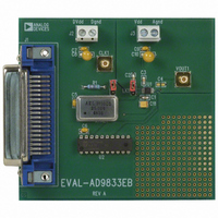
AD9833 EVALUATION BOARD
The AD9833 evaluation board allows designers to evaluate the high
performance AD9833 DDS modulator with a minimum of effort.
To prove that this device meets the waveform synthesis
requirements of users, they only require a power supply, an
IBM® compatible PC, and a spectrum analyzer, along with the
evaluation board.
The DDS evaluation kit includes a populated, tested AD9833
PCB. The evaluation board interfaces to the parallel port of an
IBM compatible PC. Software is available with the evaluation
board that allows users to easily program the AD9833. A schematic
of the evaluation board is shown in Figure 33. The software will
run on any IBM-compatible PC that has Microsoft® Windows® 95,
Windows 98, Windows ME, or Windows 2000 NT® installed.
10
11
12
13
14
15
16
17
18
19
20
21
22
23
24
25
26
27
28
29
30
31
32
33
34
35
36
1
2
3
4
5
6
7
8
9
SCLK
SDATA
FSYNC
0.1µF
MCLK
C6
SDATA
FSYNC
DVDD
SCLK
J1
R1
50Ω
0.1µF
0.1µF
DVDD
C5
DVDD
C6
2
4
6
74HCT244
OSC XTAL
DVDD
DGND
LK2
U2
U3
1
OUT
Figure 33. Evaluation Board Layout
18
16
14
Rev. C | Page 22 of 24
7
6
8
5
0.1µF
10µF
C11
C1
SCLK
SDATA
FSYNC
MCLK
CAP
DGND
3
4
AD9833
LK1
U1
USING THE AD9833 EVALUATION BOARD
The AD9833 evaluation kit is a test system designed to simplify
the evaluation of the AD9833. A technical note, located on the
supporting CD, is also available with the evaluation board that
gives users information on operating the evaluation board.
PROTOTYPING AREA
An area is available on the evaluation board for the user to add
additional circuits to the evaluation test set. Users may want to
build custom analog filters for the output or add buffers and
operational amplifiers to be used in the final application.
XO vs. EXTERNAL CLOCK
The AD9833 can operate with master clocks up to 25 MHz. A
25 MHz oscillator is included on the evaluation board. However,
this oscillator can be removed and, if required, an external
CMOS clock connected to the part.
POWER SUPPLY
Power to the AD9833 evaluation board must be provided
externally through pin connections. The power leads should be
twisted to reduce ground loops.
VDD
AGND
VDD
2
COMP
VOUT
9
0.1µF
C2
10
1
VDD
10µF
C4
C3
0.01µF
C8
VOUT
DVDD
C7
0.1µF
J2
J3
0.1µF
C9
VDD
C10
10µF
Related parts for EVAL-AD9833EBZ
Image
Part Number
Description
Manufacturer
Datasheet
Request
R


Part Number:
Description:
BOARD EVAL FOR SI270X-A
Manufacturer:
Silicon Laboratories Inc
Datasheet:

Part Number:
Description:
BUCK CONV REF DESIGN KIT IP1201
Manufacturer:
International Rectifier
Datasheet:
Part Number:
Description:
BOARD DEMO SYNC DUAL BUCK CNVTER
Manufacturer:
International Rectifier
Datasheet:
Part Number:
Description:
BOARD DEMO SYNC BUCK CONVETER
Manufacturer:
International Rectifier
Datasheet:

Part Number:
Description:
EVALBOARD/EB Omnidirectional microphone - Analog
Manufacturer:
Analog Devices
Datasheet:
Part Number:
Description:
EVALBOARD/EB Omnidirectional microphone - Analog
Manufacturer:
Analog Devices
Datasheet:


Part Number:
Description:
BOARD EVAL LED DRIVER LT3756
Manufacturer:
Linear Technology
Datasheet:

Part Number:
Description:
BOARD EVAL FOR AD7741/7742
Manufacturer:
Analog Devices Inc
Datasheet:

Part Number:
Description:
±1.7g Dual-Axis IMEMS Accelerometer Evaluation Board
Manufacturer:
Analog Devices Inc
Datasheet:

Part Number:
Description:
IC MULTIPLIER ANALOG 8-SOIC T/R
Manufacturer:
Analog Devices Inc
Datasheet:

Part Number:
Description:
IC ANALOG MULTIPLIER 8-DIP
Manufacturer:
Analog Devices Inc
Datasheet:
Part Number:
Description:
IC ANALOG MULTIPLIER 8-SOIC
Manufacturer:
Analog Devices Inc
Datasheet:
Part Number:
Description:
IC ANALOG MULTIPLIER 8-DIP
Manufacturer:
Analog Devices Inc
Datasheet: