EVAL-ADM1178EBZ Analog Devices Inc, EVAL-ADM1178EBZ Datasheet - Page 15
EVAL-ADM1178EBZ
Manufacturer Part Number
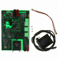
EVAL-ADM1178EBZ
Description
BOARD EVALUATION FOR ADM1178
Manufacturer
Analog Devices Inc
Specifications of EVAL-ADM1178EBZ
Main Purpose
Power Management, Hot Swap Controller
Embedded
No
Utilized Ic / Part
ADM1178
Primary Attributes
Hot Swap Controller, Digital Power Monitor, High Side MOSFET Driver
Secondary Attributes
SMBus, I2C, 3.15 V ~ 16.5 V Supply
Lead Free Status / RoHS Status
Lead free / RoHS Compliant


When the initial timing cycle terminates, the device is ready to
start a hot swap operation (assuming that the ON pin is asserted).
In the example shown in Figure 33, the ON pin is asserted at the
same time as V
starts immediately after Time Point 4. At this point, the FET
gate is charged up with a 12.5 μA current source.
At Time Point 5, the threshold voltage of the FET is reached and
the load current begins to flow. The FET is controlled to keep
the sense voltage at 100 mV (this corresponds to a maximum load
current level defined by the value of R
At Time Point 6, V
potential, and the load current has settled to its nominal level.
Figure 34 illustrates the situation where the ON pin is asserted
after V
V
V
V
SENSE
TIMER
V
GATE
CC
V
V
OUT
CC
ON
is applied.
Figure 33. Startup (ON Asserts as Power Is Applied)
(1)
CC
is applied; therefore, the hot swap operation
(2)
GATE
INITIAL TIMING
and V
CYCLE
OUT
(3)(4) (5)
have reached their full
SENSE
).
(6)
Rev. C | Page 15 of 24
HOT SWAP RETRY CYCLE ON THE ADM1178-1
With the ADM1178-1, the device turns off the FET after an
overcurrent fault and then uses the TIMER pin to time a delay
before automatically retrying to hot swap.
As with all ADM1178 devices, an overcurrent fault is timed by
charging the TIMER capacitor with a 60 μA pull-up current.
When the TIMER pin reaches 1.3 V, the fault current limit time
is reached, and the GATE pin is pulled down. On the ADM1178-1,
the TIMER pin is then pulled down with a 2 μA current sink.
When the TIMER pin reaches 0.2 V, it automatically restarts the
hot swap operation.
The cooldown period is related to C
Therefore, the retry duty cycle is as given by Equation 9.
V
t
t
V
V
SENSE
COOL
FAULT
TIMER
V
GATE
V
V
OUT
ON
CC
≈ 550 × C
Figure 34. Startup (ON Asserts After Power Is Applied)
/(t
COOL
(1)
+ t
(2)
FAULT
TIMER
INITIAL TIMING
CYCLE
) × 100% = 3.8%
ms/μF
(3)(4)
TIMER
by Equation 8.
(5)(6)
ADM1178
(7)
(8)
(9)
Related parts for EVAL-ADM1178EBZ
Image
Part Number
Description
Manufacturer
Datasheet
Request
R


Part Number:
Description:
BOARD EVAL FOR SI270X-A
Manufacturer:
Silicon Laboratories Inc
Datasheet:

Part Number:
Description:
BUCK CONV REF DESIGN KIT IP1201
Manufacturer:
International Rectifier
Datasheet:
Part Number:
Description:
BOARD DEMO SYNC DUAL BUCK CNVTER
Manufacturer:
International Rectifier
Datasheet:
Part Number:
Description:
BOARD DEMO SYNC BUCK CONVETER
Manufacturer:
International Rectifier
Datasheet:

Part Number:
Description:
EVALBOARD/EB Omnidirectional microphone - Analog
Manufacturer:
Analog Devices
Datasheet:
Part Number:
Description:
EVALBOARD/EB Omnidirectional microphone - Analog
Manufacturer:
Analog Devices
Datasheet:


Part Number:
Description:
BOARD EVAL LED DRIVER LT3756
Manufacturer:
Linear Technology
Datasheet:

Part Number:
Description:
BOARD EVAL FOR AD7741/7742
Manufacturer:
Analog Devices Inc
Datasheet:

Part Number:
Description:
±1.7g Dual-Axis IMEMS Accelerometer Evaluation Board
Manufacturer:
Analog Devices Inc
Datasheet:

Part Number:
Description:
IC MULTIPLIER ANALOG 8-SOIC T/R
Manufacturer:
Analog Devices Inc
Datasheet:

Part Number:
Description:
IC ANALOG MULTIPLIER 8-DIP
Manufacturer:
Analog Devices Inc
Datasheet:
Part Number:
Description:
IC ANALOG MULTIPLIER 8-SOIC
Manufacturer:
Analog Devices Inc
Datasheet:
Part Number:
Description:
IC ANALOG MULTIPLIER 8-DIP
Manufacturer:
Analog Devices Inc
Datasheet: