101-1218 Rabbit Semiconductor, 101-1218 Datasheet - Page 29
101-1218
Manufacturer Part Number
101-1218
Description
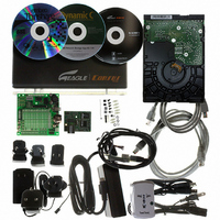
KIT APPLCTN RABBITCORE RCM4010
Manufacturer
Rabbit Semiconductor
Series
RabbitCore®r
Datasheet
1.20-101-1094.pdf
(130 pages)
Specifications of 101-1218
Main Purpose
*
Embedded
*
Utilized Ic / Part
RCM4010
Primary Attributes
*
Secondary Attributes
*
Processor To Be Evaluated
Rabbit 4000
Interface Type
Ethernet
Operating Supply Voltage
12 V
Lead Free Status / RoHS Status
Not applicable / Not applicable
Other names
316-1156


3.2.3 A/D Converter Inputs (RCM4000 only)
The following sample programs are found in the
•
•
•
•
User’s Manual
AD_CAL_ALL.C
channels with one gain using two known voltages to generate the calibration constants
for each channel. The constants will be rewritten into the user block data area.
Connect a positive voltage (for example, the power supply positive output) to analog
input channels LN0IN–LN6IN on the Prototyping Board, and connect the ground to
GND.
STDIO window once you compile and run this sample program. Remember that analog input
LN7 on the Prototyping Board is used with the thermistor and should not be used with this
sample program.
AD_CAL_CHAN.C
channel with one gain using two known voltages to generate the calibration constants
for that channel. The constants will be rewritten into the user block data area.
Connect a positive voltage to an analog input channel on the Prototyping Board, and
connect the ground to GND.
tions in the Dynamic C STDIO window. Remember that analog input LN7 on the Prototyping
Board is used with the thermistor and should not be used with this sample program.
AD_RDVOLT_ALL.C
using previously defined calibration constants. Coefficients are read from the simulated
EEPROM in the flash memory to compute equivalent voltages, and cannot be run in
RAM.
Compile and run this sample program once you have connected a positive voltage from
0–20 V DC to an analog input (except LN7) on the Prototyping Board, and ground to
GND. Follow the prompts in the Dynamic C
equivalent voltages will be displayed.
AD_SAMPLE.C
inputs. The program will continuously display the voltage (averaged over 10 samples)
that is present on the A/D converter channels (except LN7). Coefficients are read from
the simulated EEPROM in the flash memory to compute equivalent voltages, so the
sample program cannot be run in RAM.
Compile and run this sample program once you have connected a positive voltage from
0–20 V DC to an analog input (except LN7) on the Prototyping Board, and ground to
GND. Follow the prompts in the Dynamic C
equivalent voltages will be displayed. If you attach a voltmeter between the analog
input and ground, you will be able to observe that the voltage in the Dynamic C
window tracks the voltage applied to the analog input as you vary it.
NOTE: The above sample program will overwrite any existing calibration constants.
NOTE: The above sample program will overwrite any existing calibration constants.
Use a voltmeter to measure the voltage, and follow the instructions in the Dynamic C
—Demonstrates how to how to use a low level driver on single-ended
—Demonstrates how to recalibrate all the single-ended analog input
—Demonstrates how to recalibrate one single-ended analog input
—Demonstrates how to read all single-ended A/D input channels
Use a voltmeter to measure the voltage, and follow the instruc-
STDIO
STDIO
SAMPLES\RCM4000\ADC
window. Computed raw data and
window. Computed raw data and
folder.
STDIO
23
Related parts for 101-1218
Image
Part Number
Description
Manufacturer
Datasheet
Request
R

Part Number:
Description:
COMPUTER SNGLBD BL2120 FRCTNLOCK
Manufacturer:
Rabbit Semiconductor
Datasheet:

Part Number:
Description:
KIT MESH NETWORK ADD-ON RCM4510W
Manufacturer:
Rabbit Semiconductor
Datasheet:

Part Number:
Description:
KIT DEV FOR BL2500 COYOTE
Manufacturer:
Rabbit Semiconductor
Datasheet:

Part Number:
Description:
KIT APPLICATION SIMPLE SENSOR
Manufacturer:
Rabbit Semiconductor
Datasheet:

Part Number:
Description:
KIT ETHERNET INT'L RCM3720
Manufacturer:
Rabbit Semiconductor
Datasheet:
Part Number:
Description:
KIT SERIAL-ETHERNET APPLICATION
Manufacturer:
Rabbit Semiconductor

Part Number:
Description:
KIT APPLICATION MULTI-PORT S2E
Manufacturer:
Rabbit Semiconductor
Part Number:
Description:
KIT WEB SECURE EMBEDDED RCM3700
Manufacturer:
Rabbit Semiconductor
Datasheet:
Part Number:
Description:
MODULE RABBITCORE RCM3720
Manufacturer:
Rabbit Semiconductor
Datasheet:
Part Number:
Description:
MODULE RABBITCORE RCM3220
Manufacturer:
Rabbit Semiconductor
Datasheet:
Part Number:
Description:
MODULE RABBITCORE RCM3210
Manufacturer:
Rabbit Semiconductor
Datasheet:
Part Number:
Description:
COMPUTER SGL-BOARD OP6600 W/SRAM
Manufacturer:
Rabbit Semiconductor
Datasheet:
Part Number:
Description:
COMPUTER SGL-BD BL2000 SRAM/FLSH
Manufacturer:
Rabbit Semiconductor