STEVAL-IHM012V1 STMicroelectronics, STEVAL-IHM012V1 Datasheet - Page 12
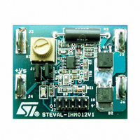
STEVAL-IHM012V1
Manufacturer Part Number
STEVAL-IHM012V1
Description
EVAL BRD POWER MOSFET/8PIN MCU
Manufacturer
STMicroelectronics
Type
Motor / Motion Controllers & Driversr
Specifications of STEVAL-IHM012V1
Design Resources
STEVAL-IHM012V1 Gerber Files STEVAL-IHM012V1 Schematic STEVAL-IHM012V1 Bill of Materials
Main Purpose
Power Management, Motor Control
Embedded
Yes, MCU, 8-Bit
Utilized Ic / Part
ST7FLITEUS5
Primary Attributes
Brush DC Motors
Secondary Attributes
DC Chopper
Product
Power Management Modules
Kit Application Type
Power Management - Motor Control
Application Sub Type
BLDC Motor
Kit Contents
Board
Rohs Compliant
Yes
Lead Free Status / RoHS Status
Lead free / RoHS Compliant
For Use With/related Products
ST7FLiteUS5
Other names
497-5861
Available stocks
Company
Part Number
Manufacturer
Quantity
Price
Company:

Part Number:
STEVAL-IHM012V1
Manufacturer:
STMicroelectronics
Quantity:
135


Software
Note:
5.1
Note:
12/18
The working principle of using a Power MOSFET to drive DC brush motor is to change the
duty cycle of the PWM control signal generated by the 12-bit autoreload timer (AT) inside the
software.
Before downloading firmware in the microcontroller, ensure that jumpers J1 and J2 are NOT
present before the input voltage is connected. Thus under normal conditions these jumpers
must be present before the input voltage is connected. See
Main.c
The battery voltage check function and the "Speed Pot" reading are implemented in this
module as described above. The reading of the "Speed Pot" and Safe Battery routine are
synchronized on the Overflow event (OVF interrupt) of the Auto-reload timer through the
"enable" flag.
Enable is true at the end of each OVF interrrupt.
The "Speed Pot" is read every 5 cycles (look at variable "count") of the Auto-reload timer.
The voltage battery is read every (10000 +1) cycles (look at the variable "counter") in
standard mode, and it will be read every (2000+1) cycles in battery safe mode.
in this way the "Speed Pot" reading and voltage battery reading won't be done in the same
PWM period.
The value of duty cycle is updated in the PWM AT OVF routine. See flowchart in
Figure 6.
Main programming flowchart
Disable Motor control
Safe_Batt = 1
System Reset
Fast Flashing
Can’t work
Waiting for
routine:
Motor
LED
<88%
Speed pot position
AR timer init
Variables init
Battery Level
Safe Batt = 0
full
While (on)
Enable = 0
ADC init
Ports init
Reading
Turn off
Voltage
Battery
MAIN
Enable
1
LED
0
<90%
Figure
Slow Flashing
LED
2.
Figure
UM0291
6.
Related parts for STEVAL-IHM012V1
Image
Part Number
Description
Manufacturer
Datasheet
Request
R

Part Number:
Description:
BOARD EVAL FOR MEMS SENSORS
Manufacturer:
STMicroelectronics
Datasheet:

Part Number:
Description:
KIT DEV STARTER ST10F276Z5
Manufacturer:
STMicroelectronics
Datasheet:

Part Number:
Description:
BOARD EVAL HDMI $ VIDEO SWITCH
Manufacturer:
STMicroelectronics
Datasheet:

Part Number:
Description:
BOARD DEMO ACCELEROMETER DIL24
Manufacturer:
STMicroelectronics
Datasheet:

Part Number:
Description:
BOARD STLM75/STDS75/ST72F651
Manufacturer:
STMicroelectronics
Datasheet:

Part Number:
Description:
EVAL BOARD 3AXIS MEMS ACCELLRMTR
Manufacturer:
STMicroelectronics
Datasheet:

Part Number:
Description:
BOARD EVAL 8BIT MICRO + TDE1708
Manufacturer:
STMicroelectronics
Datasheet:

Part Number:
Description:
EVAL BOARD A/D TS4657
Manufacturer:
STMicroelectronics
Datasheet:

Part Number:
Description:
BOARD ADAPTER 20DIP LIS3LV02DL
Manufacturer:
STMicroelectronics
Datasheet:

Part Number:
Description:
BOARD DEMO STM8S207R6/LIS331DLH
Manufacturer:
STMicroelectronics
Datasheet:

Part Number:
Description:
STMicroelectronics [RIPPLE-CARRY BINARY COUNTER/DIVIDERS]
Manufacturer:
STMicroelectronics
Datasheet:
Part Number:
Description:
STMicroelectronics [LIQUID-CRYSTAL DISPLAY DRIVERS]
Manufacturer:
STMicroelectronics
Datasheet:
Part Number:
Description:
BOARD EVAL FOR MEMS SENSORS
Manufacturer:
STMicroelectronics
Datasheet: