STEVAL-IHM012V1 STMicroelectronics, STEVAL-IHM012V1 Datasheet - Page 9
STEVAL-IHM012V1
Manufacturer Part Number
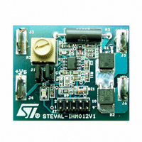
STEVAL-IHM012V1
Description
EVAL BRD POWER MOSFET/8PIN MCU
Manufacturer
STMicroelectronics
Type
Motor / Motion Controllers & Driversr
Specifications of STEVAL-IHM012V1
Design Resources
STEVAL-IHM012V1 Gerber Files STEVAL-IHM012V1 Schematic STEVAL-IHM012V1 Bill of Materials
Main Purpose
Power Management, Motor Control
Embedded
Yes, MCU, 8-Bit
Utilized Ic / Part
ST7FLITEUS5
Primary Attributes
Brush DC Motors
Secondary Attributes
DC Chopper
Product
Power Management Modules
Kit Application Type
Power Management - Motor Control
Application Sub Type
BLDC Motor
Kit Contents
Board
Rohs Compliant
Yes
Lead Free Status / RoHS Status
Lead free / RoHS Compliant
For Use With/related Products
ST7FLiteUS5
Other names
497-5861
Available stocks
Company
Part Number
Manufacturer
Quantity
Price
Company:

Part Number:
STEVAL-IHM012V1
Manufacturer:
STMicroelectronics
Quantity:
135


UM0291
4.2
4.3
So R
Equation 3
For the 7.2 cordless drill (6 cells) we have chosen V
Sensing resistor (R
The value of the sensing resistor must be chosen to guarantee the right power dissipation at
the maximum handling current and to guarantee at least 300 mV in order to read the motor
current using the 10bit on board microcontroller ADC.
The evaluation board has been set and tested for a 7.2 DC brush motor.
The maximum current for the used motor is I
It follows that:
Equation 4
Power MOSFET
The choice of the Power MOSFET begins by choosing devices that can handle the required
current, given an adequate thermal dissipation path.
Here we have the equations for calculating the power dissipation of these MOSFETs and
determining the temperature at which they operate.
To determine whether or not a Power MOSFET is suitable for that application, we must
calculate its power dissipation, which consists mainly of resistive and switching losses:
Equation 5
One of the most severe tests for electronic drills is to evaluate the transistor's performance
with the rotor blocked. In this case the rotor remains fixed for a minimum time of 20 seconds,
while the Power MOSFET runs at the maximum duty cycle at maximum RMS current (in this
case is fixed by the safety routine in the microcontroller)
Equation 6
Where:
I
The operating junction temperature is:
Equation 7
LOAD
S
= maximum handling current by the motor.
will be:
PD
PD
SENS
TOT
TOT
T
≅
J
R
=
PD
=
)
S
PD
T
RESISTIVE
=
A
R
RESISTIVE
+
-----------------------------------------------
I
SENS
zener MIN
R
V
TH TOT
Smin
MAX
–
–
=
=
0.05
–
= 8 A.
+
R
V
+
Smin
PD
DS on
•
ZD
I
PD
OUT
(
SWITCHING
TOT
= 88% V
)
•
I
LOAD
Application design procedure
2
Nominal
and thus R
S
≅ 68 Ω .
9/18
Related parts for STEVAL-IHM012V1
Image
Part Number
Description
Manufacturer
Datasheet
Request
R

Part Number:
Description:
BOARD EVAL FOR MEMS SENSORS
Manufacturer:
STMicroelectronics
Datasheet:

Part Number:
Description:
KIT DEV STARTER ST10F276Z5
Manufacturer:
STMicroelectronics
Datasheet:

Part Number:
Description:
BOARD EVAL HDMI $ VIDEO SWITCH
Manufacturer:
STMicroelectronics
Datasheet:

Part Number:
Description:
BOARD DEMO ACCELEROMETER DIL24
Manufacturer:
STMicroelectronics
Datasheet:

Part Number:
Description:
BOARD STLM75/STDS75/ST72F651
Manufacturer:
STMicroelectronics
Datasheet:

Part Number:
Description:
EVAL BOARD 3AXIS MEMS ACCELLRMTR
Manufacturer:
STMicroelectronics
Datasheet:

Part Number:
Description:
BOARD EVAL 8BIT MICRO + TDE1708
Manufacturer:
STMicroelectronics
Datasheet:

Part Number:
Description:
EVAL BOARD A/D TS4657
Manufacturer:
STMicroelectronics
Datasheet:

Part Number:
Description:
BOARD ADAPTER 20DIP LIS3LV02DL
Manufacturer:
STMicroelectronics
Datasheet:

Part Number:
Description:
BOARD DEMO STM8S207R6/LIS331DLH
Manufacturer:
STMicroelectronics
Datasheet:

Part Number:
Description:
STMicroelectronics [RIPPLE-CARRY BINARY COUNTER/DIVIDERS]
Manufacturer:
STMicroelectronics
Datasheet:
Part Number:
Description:
STMicroelectronics [LIQUID-CRYSTAL DISPLAY DRIVERS]
Manufacturer:
STMicroelectronics
Datasheet:
Part Number:
Description:
BOARD EVAL FOR MEMS SENSORS
Manufacturer:
STMicroelectronics
Datasheet: