STEVAL-IHM012V1 STMicroelectronics, STEVAL-IHM012V1 Datasheet - Page 8
STEVAL-IHM012V1
Manufacturer Part Number
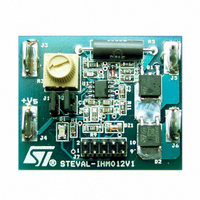
STEVAL-IHM012V1
Description
EVAL BRD POWER MOSFET/8PIN MCU
Manufacturer
STMicroelectronics
Type
Motor / Motion Controllers & Driversr
Specifications of STEVAL-IHM012V1
Design Resources
STEVAL-IHM012V1 Gerber Files STEVAL-IHM012V1 Schematic STEVAL-IHM012V1 Bill of Materials
Main Purpose
Power Management, Motor Control
Embedded
Yes, MCU, 8-Bit
Utilized Ic / Part
ST7FLITEUS5
Primary Attributes
Brush DC Motors
Secondary Attributes
DC Chopper
Product
Power Management Modules
Kit Application Type
Power Management - Motor Control
Application Sub Type
BLDC Motor
Kit Contents
Board
Rohs Compliant
Yes
Lead Free Status / RoHS Status
Lead free / RoHS Compliant
For Use With/related Products
ST7FLiteUS5
Other names
497-5861
Available stocks
Company
Part Number
Manufacturer
Quantity
Price
Company:

Part Number:
STEVAL-IHM012V1
Manufacturer:
STMicroelectronics
Quantity:
135


Application design procedure
4
4.1
8/18
Application design procedure
This evaluation board can be configured for different DC brush motors: 7.2 V - 18 V, here we
have an example of design procedure for 7.2 V DC brush motor. If the user wants to
configure the Evaluation board for other motors, there are the following adjustments to do:
●
●
●
Zener regulator circuit
The power supply is shown in
following equation:
Equation 1
where
Figure 3.
Equation 2
where I
considering that the active on-chip peripherals are working together and thus I
The current to hold the V
In the NiCd and NiMH batteries the cell voltage is 1.2 V and in discharge condition it must be
more than 1 V (to avoid damaging them). We have to assure that the microcontroller is
supplied with 5 V in all conditions and thus we have chosen V
battery.
Zener regulator circuit: R
Sensing resistor: R
Power MOSFET (evaluating the operating junction temperature),
–
–
–
OUT
V
VZD = the voltage drop, V, across the Zener diode, and
R
S
S
is the maximum absorbed current by the microcontroller. We can estimate I
= the resistor.
Zener regulator circuit
= Supply voltage,
SENS
Z
= 5.1 V is I
,
S
Figure
,
I
IN
3. The input current I
zener_MIN
=
I
IN
I
zener MIN
=
V
----------------------- -
S
–
R
–
= 5 mA (see datasheet).
S
V
ZD
+
I
OUT
IN
can be expressed by the
S
= V
Smin
= 88% V
OUT
Nominal
= 8 mA.
UM0291
OUT
of
Related parts for STEVAL-IHM012V1
Image
Part Number
Description
Manufacturer
Datasheet
Request
R

Part Number:
Description:
BOARD EVAL FOR MEMS SENSORS
Manufacturer:
STMicroelectronics
Datasheet:

Part Number:
Description:
KIT DEV STARTER ST10F276Z5
Manufacturer:
STMicroelectronics
Datasheet:

Part Number:
Description:
BOARD EVAL HDMI $ VIDEO SWITCH
Manufacturer:
STMicroelectronics
Datasheet:

Part Number:
Description:
BOARD DEMO ACCELEROMETER DIL24
Manufacturer:
STMicroelectronics
Datasheet:

Part Number:
Description:
BOARD STLM75/STDS75/ST72F651
Manufacturer:
STMicroelectronics
Datasheet:

Part Number:
Description:
EVAL BOARD 3AXIS MEMS ACCELLRMTR
Manufacturer:
STMicroelectronics
Datasheet:

Part Number:
Description:
BOARD EVAL 8BIT MICRO + TDE1708
Manufacturer:
STMicroelectronics
Datasheet:

Part Number:
Description:
EVAL BOARD A/D TS4657
Manufacturer:
STMicroelectronics
Datasheet:

Part Number:
Description:
BOARD ADAPTER 20DIP LIS3LV02DL
Manufacturer:
STMicroelectronics
Datasheet:

Part Number:
Description:
BOARD DEMO STM8S207R6/LIS331DLH
Manufacturer:
STMicroelectronics
Datasheet:

Part Number:
Description:
STMicroelectronics [RIPPLE-CARRY BINARY COUNTER/DIVIDERS]
Manufacturer:
STMicroelectronics
Datasheet:
Part Number:
Description:
STMicroelectronics [LIQUID-CRYSTAL DISPLAY DRIVERS]
Manufacturer:
STMicroelectronics
Datasheet:
Part Number:
Description:
BOARD EVAL FOR MEMS SENSORS
Manufacturer:
STMicroelectronics
Datasheet: