STEVAL-TLL005V1 STMicroelectronics, STEVAL-TLL005V1 Datasheet - Page 25
STEVAL-TLL005V1
Manufacturer Part Number
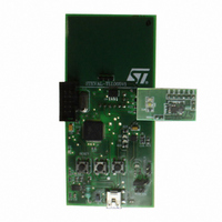
STEVAL-TLL005V1
Description
BOARD EVAL PWR FLASH STCF03/ST7
Manufacturer
STMicroelectronics
Datasheets
1.STCF03PNR.pdf
(35 pages)
2.STEVAL-TLL005V1.pdf
(4 pages)
3.STEVAL-TLL005V1.pdf
(10 pages)
Specifications of STEVAL-TLL005V1
Design Resources
STEVAL-TLL005V1 Bill of Materials
Main Purpose
Lighting, Camera Flash
Embedded
Yes, MCU, 8-Bit
Utilized Ic / Part
STCF03
Primary Attributes
Camera Flash, I2C Controlled, Flash and Torch Mode
Secondary Attributes
Li-Ion Battery, Battery Charger Circuit, GUI
Description/function
Flash Driver Evaluation Board
Core Chip
STCF03
Topology
Buck-Boost
No. Of Outputs
1
Dimming Control Type
I2C
Development Tool Type
Hardware - Eval/Demo Board
Supported Devices
STCF03 Device Type
For Use With
497-8431 - BOARD EVAL FLASH DRIVER STCF03
Lead Free Status / RoHS Status
Lead free / RoHS Compliant
For Use With/related Products
STCF03, ST7
Other names
497-8207


STCF03
9
9.1
9.2
9.3
9.4
Detailed description
PowerON reset
This mode is initiated by applying a supply voltage above the V
value. An internal timing (~1 µs) defines the duration of this status. The logic blocks are
powered, but the device doesn't respond to any input. The registers are reset to their default
values, the ATN and SDA pins are in high-Z, and the I²C slave address is internally set by
reading the ADD pin configuration. After the internally defined time has elapsed, the
STCF03 automatically enters the Stand-by mode.
Shutdown, shutdown with NTC
In this mode only the I²C interface is alive, accepting I²C commands and register settings.
The device enters this mode: automatically from Power ON reset status; by resetting the
PWR_ON bit from other operation modes. Power consumption is at the minimum (1 µA max)
if NTC is not activated (NTC_ON=0). If PWR_ON and NTC_ON is set, the T1 is switched
ON (see the block diagram), allowing the microprocessor to measure the LED temperature
through its A/D converter. When NTC circuits are active and the V
typ. current consumption is increased to 1 µA, then it is recommended not to leave the
STCF03 in this status if battery drain has to be minimized.
Ready mode
In this mode all internal blocks are turned ON, but the DC-DC converter is disabled and the
White LED is disconnected. The NTC circuit can be activated to monitor the temperature of
the LED and I²C commands and register settings are allowed to be executed immediately.
Only in this mode the auxiliary LED is operational and can be turned ON and set at the
desired brightness using the AUX REGISTER. The device enters this mode: from Stand-by
by setting the PWR_ON bit; from flash operation by resetting the TRIG pin or the TRIG_EN
bit or automatically from flash operation when the time counter reaches zero; from torch
operation by resetting the TCH_ON bit. The device automatically enters this mode also
when an overload or an abnormal condition has been detected during flash or torch
operation
Single or multiple Flash using external (microprocessor)
temporization
To avoid the I²C bus time latency, it is recommended to use the dedicated TRIG pin to define
the flash duration (hard-triggering). The TRIG_EN bit of CMD_REG should be set before
starting each flash operation, because it could have been reset automatically in the previous
flash operation. Flash duration is determined by the pulse length that drives the TRIG pin.
As soon as the flash is activated, the system needs typically 1.2 ms to ramp up the output
current on the power LED. The internal time counter will time-out flash operation and keep
the LED dissipated energy within safe limits in case of software deadlock; FTIM register has
to be set first, either in stand-by or in ready mode. Multiple flashes are possible by strobing
the TRIG pin. Time out counter will cumulate every flash on-time until the defined time out is
reached unless it is reloaded by updating the CMD_REG. If single or multiple flash
operation is timed-out, the device automatically goes in Ready mode by resetting the
(Table 16: Status register
Doc ID 13169 Rev 7
details:).
PW_ON RESET
REF-EXT
Detailed description
is present, the
threshold
25/35
Related parts for STEVAL-TLL005V1
Image
Part Number
Description
Manufacturer
Datasheet
Request
R

Part Number:
Description:
BOARD EVAL FOR ST802RT1
Manufacturer:
STMicroelectronics
Datasheet:

Part Number:
Description:
EVAL BOARD 100 BASE T
Manufacturer:
STMicroelectronics
Datasheet:

Part Number:
Description:
BOARD ELECT FISCAL CASH REGISTER
Manufacturer:
STMicroelectronics
Datasheet:
Part Number:
Description:
BOARD EVAL FOR ST802RT1A
Manufacturer:
STMicroelectronics
Datasheet:

Part Number:
Description:
2 kW/100 V RF demonstration board for 3 T MRI based on the STAC4932B
Manufacturer:
STMICROELECTRONICS [STMicroelectronics]
Datasheet:

Part Number:
Description:
BOARD EVAL FOR MEMS SENSORS
Manufacturer:
STMicroelectronics
Datasheet:
Part Number:
Description:
EVALBOARD/STEVAL-ISV014V1
Manufacturer:
STMicroelectronics

Part Number:
Description:
BOARD EVAL FOR VACUUM CLEANER
Manufacturer:
STMicroelectronics
Datasheet:

Part Number:
Description:
KIT DEV STARTER ST10F276Z5
Manufacturer:
STMicroelectronics
Datasheet:

Part Number:
Description:
BOARD LED CTLR/DVR STLED316S
Manufacturer:
STMicroelectronics
Datasheet:
Part Number:
Description:
STMicroelectronics [RIPPLE-CARRY BINARY COUNTER/DIVIDERS]
Manufacturer:
STMicroelectronics
Datasheet:
Part Number:
Description:
STMicroelectronics [LIQUID-CRYSTAL DISPLAY DRIVERS]
Manufacturer:
STMicroelectronics
Datasheet:
Part Number:
Description:
BOARD EVAL FOR MEMS SENSORS
Manufacturer:
STMicroelectronics
Datasheet: