SI5338-EVB Silicon Laboratories Inc, SI5338-EVB Datasheet - Page 13
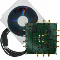
SI5338-EVB
Manufacturer Part Number
SI5338-EVB
Description
BOARD EVALUATION SI5338
Manufacturer
Silicon Laboratories Inc
Datasheet
1.SI5338B-A-GM.pdf
(42 pages)
Specifications of SI5338-EVB
Main Purpose
Timing, Clock Generator
Embedded
No
Utilized Ic / Part
Si5338
Primary Attributes
160 kHz to 700 MHz in LVPECL/LVDS,
Secondary Attributes
USB Based GUI to Program, I2C/SMBus Compatible Interface, 1.8, 2.5, or 3.3 V
For Use With/related Products
Si5330/34/38 Family
Lead Free Status / RoHS Status
Lead free / RoHS Compliant
Lead Free Status / RoHS Status
Lead free / RoHS Compliant, Lead free / RoHS Compliant
Other names
336-1556


Table 12. Jitter Specifications
(V
Parameter
Random Jitter
(12 kHz–20 MHz)
Deterministic Jitter
Total Jitter
(12 kHz–20 MHz)
Notes:
DD
1. All jitter measurements apply for LVDS/HCSL/LVPECL output format with a low noise differential input clock and are
2. For best jitter performance, keep the single ended clock input slew rates at Pins 3 and 4 more than 1.0 V/ns and the
3. All jitter data in this table is based upon all output formats being differential. When single-ended outputs are used, there
4. D
5. Output MultiSynth in Integer mode.
6. All output clocks 100 MHz HCSL format. Jitter is from the PCIE jitter filter combination that produces the highest jitter.
7. Input frequency to the Phase Detector between 25 and 40 MHz and any output frequency > 5 MHz.
8. Measured in accordance with JEDEC standard 65.
9. Rj is multiplied by 14; estimate the pp jitter from Rj over 2
= 1.8 V –5% to +10%, 2.5 V ±10%, or 3.3 V ±10%, T
made with an Agilent 90804 oscilloscope. All RJ measurements use RJ/DJ separation.
differential clock input slew rates more than 0.3 V/ns.
is the potential that the output jitter may increase due to the nature of single-ended outputs. If your configuration
implements any single-ended output and any output is required to have jitter less than 3 ps rms, contact Silicon Labs
for support to validate your configuration and ensure the best jitter performance. In many configurations, CMOS
outputs have little to no effect upon jitter.
See AN562 for details.
J
for PCI and GbE is < 5 ps pp
T
(See Note
J
= D
Symbol
1,2,3
R
D
J
+14xR
J
J
(Continued)
9
)
J
Output and feedback
MultiSynth in integer or
fractional mode
Output MultiSynth
operated in fractional
mode
Output MultiSynth
operated in integer
mode
Output MultiSynth
operated in fractional
mode
Output MultiSynth
operated in integer
mode
Test Condition
A
7
7
7
7
Rev. 1.0
= –40 to 85 °C)
12
rising edges.
7
Min
—
—
—
—
—
Typ
0.7
13
12
3
2
Max
1.5
15
10
36
20
Si5338
ps pk-pk
ps pk-pk
ps pk-pk
ps pk-pk
ps RMS
Unit
13
Related parts for SI5338-EVB
Image
Part Number
Description
Manufacturer
Datasheet
Request
R

Part Number:
Description:
KIT PROG FIELD SI5338/4/0
Manufacturer:
Silicon Laboratories Inc
Datasheet:

Part Number:
Description:
Programmers & Debuggers Si5338/4/0 field programming kit
Manufacturer:
Silicon Laboratories Inc
Datasheet:
Part Number:
Description:
SMD/C°/SINGLE-ENDED OUTPUT SILICON OSCILLATOR
Manufacturer:
Silicon Laboratories Inc
Part Number:
Description:
Manufacturer:
Silicon Laboratories Inc
Datasheet:
Part Number:
Description:
N/A N/A/SI4010 AES KEYFOB DEMO WITH LCD RX
Manufacturer:
Silicon Laboratories Inc
Datasheet:
Part Number:
Description:
N/A N/A/SI4010 SIMPLIFIED KEY FOB DEMO WITH LED RX
Manufacturer:
Silicon Laboratories Inc
Datasheet:
Part Number:
Description:
N/A/-40 TO 85 OC/EZLINK MODULE; F930/4432 HIGH BAND (REV E/B1)
Manufacturer:
Silicon Laboratories Inc
Part Number:
Description:
EZLink Module; F930/4432 Low Band (rev e/B1)
Manufacturer:
Silicon Laboratories Inc
Part Number:
Description:
I°/4460 10 DBM RADIO TEST CARD 434 MHZ
Manufacturer:
Silicon Laboratories Inc
Part Number:
Description:
I°/4461 14 DBM RADIO TEST CARD 868 MHZ
Manufacturer:
Silicon Laboratories Inc
Part Number:
Description:
I°/4463 20 DBM RFSWITCH RADIO TEST CARD 460 MHZ
Manufacturer:
Silicon Laboratories Inc
Part Number:
Description:
I°/4463 20 DBM RADIO TEST CARD 868 MHZ
Manufacturer:
Silicon Laboratories Inc
Part Number:
Description:
I°/4463 27 DBM RADIO TEST CARD 868 MHZ
Manufacturer:
Silicon Laboratories Inc
Part Number:
Description:
I°/4463 SKYWORKS 30 DBM RADIO TEST CARD 915 MHZ
Manufacturer:
Silicon Laboratories Inc