DTMFDECODER-RD Silicon Laboratories Inc, DTMFDECODER-RD Datasheet - Page 167
DTMFDECODER-RD
Manufacturer Part Number
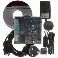
DTMFDECODER-RD
Description
KIT REF DESIGN DTMF DECODER
Manufacturer
Silicon Laboratories Inc
Specifications of DTMFDECODER-RD
Mfg Application Notes
DTMF Decoder Ref Design AppNote
Main Purpose
Telecom, DTMF Decoder
Embedded
No
Utilized Ic / Part
C8051F300
Primary Attributes
8kHz Sampling Rate ADC
Secondary Attributes
16 Goertzel Filters
Processor To Be Evaluated
C8051F300
Interface Type
RS-232
Lead Free Status / RoHS Status
Contains lead / RoHS non-compliant
Lead Free Status / RoHS Status
Lead free / RoHS Compliant, Contains lead / RoHS non-compliant
Other names
336-1283


16.4. Register Descriptions for PCA
Following are detailed descriptions of the special function registers related to the operation of the PCA.
Bit7:
Bit6:
Bits5–3: UNUSED. Read = 000b, Write = don't care.
Bit2:
Bit1:
Bit0:
R/W
CF
Bit7
CF: PCA Counter/Timer Overflow Flag.
Set by hardware when the PCA Counter/Timer overflows from 0xFFFF to 0x0000. When the
Counter/Timer Overflow (CF) interrupt is enabled, setting this bit causes the CPU to vector
to the PCA interrupt service routine. This bit is not automatically cleared by hardware and
must be cleared by software.
CR: PCA Counter/Timer Run Control.
This bit enables/disables the PCA Counter/Timer.
0: PCA Counter/Timer disabled.
1: PCA Counter/Timer enabled.
CCF2: PCA Module 2 Capture/Compare Flag.
This bit is set by hardware when a match or capture occurs. When the CCF2 interrupt is
enabled, setting this bit causes the CPU to vector to the PCA interrupt service routine. This
bit is not automatically cleared by hardware and must be cleared by software.
CCF1: PCA Module 1 Capture/Compare Flag.
This bit is set by hardware when a match or capture occurs. When the CCF1 interrupt is
enabled, setting this bit causes the CPU to vector to the PCA interrupt service routine. This
bit is not automatically cleared by hardware and must be cleared by software.
CCF0: PCA Module 0 Capture/Compare Flag.
This bit is set by hardware when a match or capture occurs. When the CCF0 interrupt is
enabled, setting this bit causes the CPU to vector to the PCA interrupt service routine. This
bit is not automatically cleared by hardware and must be cleared by software.
R/W
CR
Bit6
SFR Definition 16.1. PCA0CN: PCA Control
R/W
Bit5
—
R/W
Bit4
—
Rev. 2.9
R/W
Bit3
—
CCF2
R/W
Bit2
C8051F300/1/2/3/4/5
CCF1
R/W
Bit1
(bit addressable)
CCF0
R/W
Bit0
SFR Address:
00000000
Reset Value
0xD8
167
Related parts for DTMFDECODER-RD
Image
Part Number
Description
Manufacturer
Datasheet
Request
R

Part Number:
Description:
SMD/C°/SINGLE-ENDED OUTPUT SILICON OSCILLATOR
Manufacturer:
Silicon Laboratories Inc
Part Number:
Description:
Manufacturer:
Silicon Laboratories Inc
Datasheet:
Part Number:
Description:
N/A N/A/SI4010 AES KEYFOB DEMO WITH LCD RX
Manufacturer:
Silicon Laboratories Inc
Datasheet:
Part Number:
Description:
N/A N/A/SI4010 SIMPLIFIED KEY FOB DEMO WITH LED RX
Manufacturer:
Silicon Laboratories Inc
Datasheet:
Part Number:
Description:
N/A/-40 TO 85 OC/EZLINK MODULE; F930/4432 HIGH BAND (REV E/B1)
Manufacturer:
Silicon Laboratories Inc
Part Number:
Description:
EZLink Module; F930/4432 Low Band (rev e/B1)
Manufacturer:
Silicon Laboratories Inc
Part Number:
Description:
I°/4460 10 DBM RADIO TEST CARD 434 MHZ
Manufacturer:
Silicon Laboratories Inc
Part Number:
Description:
I°/4461 14 DBM RADIO TEST CARD 868 MHZ
Manufacturer:
Silicon Laboratories Inc
Part Number:
Description:
I°/4463 20 DBM RFSWITCH RADIO TEST CARD 460 MHZ
Manufacturer:
Silicon Laboratories Inc
Part Number:
Description:
I°/4463 20 DBM RADIO TEST CARD 868 MHZ
Manufacturer:
Silicon Laboratories Inc
Part Number:
Description:
I°/4463 27 DBM RADIO TEST CARD 868 MHZ
Manufacturer:
Silicon Laboratories Inc
Part Number:
Description:
I°/4463 SKYWORKS 30 DBM RADIO TEST CARD 915 MHZ
Manufacturer:
Silicon Laboratories Inc
Part Number:
Description:
N/A N/A/-40 TO 85 OC/4463 RFMD 30 DBM RADIO TEST CARD 915 MHZ
Manufacturer:
Silicon Laboratories Inc
Part Number:
Description:
I°/4463 20 DBM RADIO TEST CARD 169 MHZ
Manufacturer:
Silicon Laboratories Inc