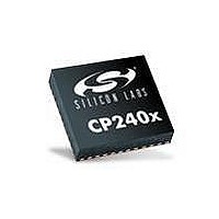
CP2400AB Silicon Laboratories Inc, CP2400AB Datasheet - Page 16

CP2400AB
Manufacturer Part Number
CP2400AB
Description
BOARD EVAL SPI LCD DRIVER CP2400
Manufacturer
Silicon Laboratories Inc
Specifications of CP2400AB
Main Purpose
LCD Development
Embedded
No
Utilized Ic / Part
CP2400
Primary Attributes
I²C, SMBus Interfaces
Secondary Attributes
Up to 128 segments
Product
Microcontroller Accessories
Core Processor
CP2400
Clock Speed
20 MHz
Interface Type
SPI
Timers
2
Operating Supply Voltage
1.8 V to 3.6 V
Cpu Core
CP2400
Lead Free Status / RoHS Status
Contains lead / RoHS non-compliant
Lead Free Status / RoHS Status
Lead free / RoHS Compliant, Contains lead / RoHS non-compliant
Other names
336-1857
CP2400/1-DK
7.2. Target Board Power Options and Current Measurement
The C8051F930 Target Board supports three power options, selectable by the three-way header (J10/J11). The
power options vary based on the configuration (one-cell or two-cell mode) selected by SW4. Power to the MCU
may be switched on/off using the power switch (SW5). Important Note: The power switch (SW5) must be in the
OFF position prior to switching between one-cell and two-cell mode using SW4. The power options are
described in the paragraphs below.
7.2.1. Wall Power
When the J10/J11 three-way header is set to WALL_PWR, the C8051F930 Target Board may be powered from the
following power sources:
All the three power sources are ORed together using reverse-biased diodes (D1, D2, D3), eliminating the need for
headers to choose between the sources. The target board will operate as long as any one of the power sources is
present. The ORed power is regulated to a 3.3 V dc voltage using a LDO regulator (U2). The output of the regulator
powers the +3 VD net on the target board.
If SW4 is configured to select two-cell mode, the VBAT supply net on the target board is powered directly from the
+3 VD net. If SW4 is configured to select one-cell mode, the VBAT supply net is powered directly from the +1 VD.
This power supply net takes +3 VD and passes it through a 1.65 V LDO. The LDO’s output voltage is variable and
can be set by changing the value of resistor R32.
7.2.2. AAA Battery
When the J10/J11 three-way header is set to AAA_BAT, the C8051F930 Target Board may be powered from a
single AAA battery inserted in BT1 or from the series combination of the AAA batteries inserted in BT1 and BT2. A
single battery is selected when SW4 is configured to one-cell mode. The two AAA batteries configured in series to
provide a voltage of ~3 V are selected when SW4 is configured to two-cell mode.
7.2.3. Coin Cell Battery
When the J10/J11 three-way header is set to COIN_CELL, the C8051F930 Target Board may be powered from a
single 1.5 V Alkaline (A76) or Silver Oxide (357) button cell inserted in BT4 or from a single 3 V Lithium (CR2032)
coin cell inserted in BT3. The button cell (BT4) is selected when SW4 is configured to one-cell mode, and the coin
cell (BT3) is selected when SW4 is configured to two-cell mode.
16
9 VDC power using the ac to dc power adapter (P2)
5 VDC USB VBUS power from PC via the USB Debug Adapter (J9)
5 VDC USB VBUS power from PC via the CP2103 USB connector (P3)
AAA_BAT
AAA_BAT
AAA_BAT
COIN_CELL
WALL_PWR
COIN_CELL
WALL_PWR
COIN_CELL
WALL_PWR
Rev. 0.1
J11
J11
J11
VBAT
VBAT
VBAT


