EVAL-AD7674CBZ Analog Devices Inc, EVAL-AD7674CBZ Datasheet
EVAL-AD7674CBZ
Specifications of EVAL-AD7674CBZ


Related parts for EVAL-AD7674CBZ


EVAL-AD7674CBZ Summary of contents
Page 1
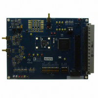
... AD764x/AD765x/AD766x/AD767x/AD795x utilizing this evaluation board. The converter installed is an LQFP however, the LFCSP can also be mounted. The evaluation board is ideal for use with either the Analog Devices EVAL-CONTROL-BRD2 or EVAL-CONTROL-BRD3 (EVAL-CONTROL-BRDX stand-alone system. The design offers the flexibility of applying external control signals and is capable of generating conversion results on parallel 14- bit, 16-bit or 18-bit wide buffered outputs ...
Page 2
... Conversion Control/ Master Clock............................................ 3 Analog Input ................................................................................. 3 Power Supplies and Grounding .................................................. 4 Using the Eval-AD762X/AD765X/AD766X/ AD767XCB as Stand-Alone................................................................................... 4 Supplying Power for Stand-Alone use ....................................... 4 Evaluation Board Setting for Bipolar ADC Input Configurations .............................................................................. 5 Schematics/PCB Layout............................................................... 5 Running the EVALAD76XXCB Software ................................. 5 Description............................... Error! Bookmark not defined. Hardware Setup ............................................................................ 5 LIST OF FIGURES Figure 1 ...
Page 3
... EVAL-CONTROL BRDX, the gate array, U10, provides the necessary control signals for conversion and buffers the ADC data. The evaluation board is a flexible design that enables the user to choose among many different board configurations, analog signal conditioning, reference, and different modes of conversion data ...
Page 4
... P3 when using with the EVAL-CONTROL-BRDX USING THE EVAL-AD762X/AD765X/AD766X/ AD767XCB AS STAND-ALONE Using the evaluation board as stand-alone does not require the EVAL-CONTROL-BRDX nor does it require use of the accompanied software. When the CONTROL input to the gate array is LOW, which is pulled down by default, the gate array provides the necessary signals for conversion and buffers the conversion data ...
Page 5
... EVAL AD977CB EVAL AD977ACB HARDWARE SETUP System Requirements • Evaluation Board • Evaluation Control Board 3 (or Board 2, not in production any longer) • AC Power Supply (AC 14V/1A source - can be purchased from ADI) • IEEE 1284 Compliant Parallel Port Cable (if not supplied) • DC source (low noise for checking different input ranges) • ...
Page 6
... AC test, apply a sinusoidal signal to the evaluation board at the SMB inputs J1 for IN+ and J2 for IN-. Low distortion, better than 100dB, is required to allow true evaluation of the part. One possibility is to filter the input signal from the AC source. There is no suggested bandpass filter but consideration should be taken in the choice. Furthermore, if ...
Page 7
... Buffer amplifier positive supply: Selection of +12V, +5V or AVDD when using EVAL-CONTROL- BRDX or voltages on SJ1 in stand alone mode. ADC digital supply voltage: Selection of +2.5V or VDIG (+5V) when using EVAL-CONTROL-BRDX or voltage on SJ2 in stand-alone mode. ADC analog supply voltage: Selection of +2.5V, +5V or EXT when using EVAL-CONTROL-BRDX Reference buffer: BUFF = use U2 to buffer or amplify reference source ...
Page 8
... EVAL-AD76XXCB Position Name Default Position 1 RESET LOW 2 PD LOW 3 PDBUF LOW 4 PDREF LOW Table 6.Test Points Test Available Type Point Signal TP1 BUSY Output TP2 A0/M0 Input TP3 SIG+ Input TP4 AGND GND TP5 REF Input/Output TP7 DGND GND TP8 CNVST ...
Page 9
... Preliminary Technical Data GND 2 +VIN 2 DGND 17 DGND 20 AGND 1 AVDD 2 DVDD 19 OVDD 2.5/3v 8 GND 4 Figure 2. Schematic, Analog Rev. PrW | Page EVAL-AD76XXCB A/B OB/2C 5 WARP 6 IMPULSE 7 SER/PAR 8 RESET 33 P BYTESWA ...
Page 10
... EVAL-AD76XXCB Preliminary Technical Data 3.3V 103 3.3V 77 3.3V 31 3.3V GND 6 102 VIO GND 127 90 VIO GND 104 76 VIO GND 91 54 VIO GND 78 30 VIO GND 55 18 VIO GND 32 5 VIO GND 19 126 VIO 7 Figure 3. Schematic, Digital Rev. PrW | Page ...
Page 11
... Preliminary Technical Data SD 6 GND GND GND 5 5 Figure 4. Schematic, Power Rev. PrW | Page EVAL-AD76XXCB ...
Page 12
... EVAL-AD76XXCB Preliminary Technical Data Figure 5. Top Side Silk-Screen Figure 6. Top Layer Rev. PrW | Page ...
Page 13
... Preliminary Technical Data Figure 7. Ground Layer Figure 8. Shield Layer Rev. PrW | Page EVAL-AD76XXCB ...
Page 14
... EVAL-AD76XXCB Figure 9. Bottom Side Layer Figure 10. Bottom Side Silk-Screen Rev. PrW | Page Preliminary Technical Data ...
Page 15
... This window allow the samples to be taken once (F3) or continuous (F4). Also selects: Help screen, Save data (F5), Print (F8) and Quit (F10). The Help menu shows a description of the functionality of the chosen command. 2) The part under evaluation is chosen from this menu. The device must be selected second. 4) This window is used to select the ...
Page 16
... EVAL-AD76XXCB These control the choice of chart type and X-units. Chart type selection of Histogram or Time and X-units of hexadecimal or Volts. The results are displayed in this chart. Also, the cursor (yellow) can be dragged desired location where the X-axis values and the Y-axis value will be displayed. ...
Page 17
... X-axis values and the Y-axis value will be displayed. Choice of either a Kaiser window or a Blackmann- Harris window from the is menu. Figure 13. FFT Screen Rev. PrW | Page EVAL-AD76XXCB AC test results are displayed here. Also the choice of viewing the amplitude of a certain FFT component can be selected from the FFT component menu. ...
Page 18
... EVAL-AD76XXCB The AC test can also be displayed in the Time Domain as shown below. To view the Time domain output, select Time in this menu. Figure 14. Time-Domain Screen Rev. PrW | Page Preliminary Technical Data ...
Page 19
... X-axis values and the Y-axis value will be displayed. The decimation ratio (Dratio) and number of Ksamples are entered here. The Nyquist frequency is displayed here as: F NYQUIST Figure 15. Decimated (Averaging) Screen Rev. PrW | Page EVAL-AD76XXCB F = SAMPLE RATIO ...
Page 20
... EVAL-AD76XXCB This selects the interface mode. Any of the four serial modes can be used to program the ADC through the Serial Programmable Port As per this informative description, the software will collect data every ten samples from the two sets of data entered in the “A” and “B” configurations through the Serial Programmable Serial Port (SPP) ...
Page 21
... Preliminary Technical Data ORDERING INFORMATION ORDERING GUIDE Evaluation Board Model Product EVAL-AD7610CB AD7610ASTZ/ACPZ EVAL-AD7612CB AD7612ASTZ/ACPZ EVAL-AD7621CB AD7621AST/ACP EVAL-AD7622CB AD7622BSTZ/BCPZ EVAL-AD7623CB AD7623AST/ACP EVAL-AD7631CB AD7631ASTZ/ACPZ EVAL-AD7634CB AD7634ASTZ/ACPZ EVAL-AD7641CB AD7641BSTZ/BCPZ EVAL-AD7643CB AD7643BSTZ/BCPZ EVAL-AD7650CB AD7650AST/ACP EVAL-AD7651CB AD7651AST/ACP EVAL-AD7652CB AD7652AST/ACP EVAL-AD7653CB AD7653AST/ACP EVAL-AD7654CB AD7654AST/ACP EVAL-AD7655CB AD7655AST/ACP ...
Page 22
... EVAL-AD76XXCB NOTES © 2006 Analog Devices, Inc. All rights reserved. Trademarks and registered trademarks are the property of their respective owners. PR03367-0-10/06(PrW) Preliminary Technical Data Rev. PrW | Page ...