CRD4525-Q1 Cirrus Logic Inc, CRD4525-Q1 Datasheet - Page 69
CRD4525-Q1
Manufacturer Part Number
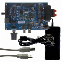
CRD4525-Q1
Description
REFERENCE BOARD FOR CS4525 PWM
Manufacturer
Cirrus Logic Inc
Series
Popguard®r
Specifications of CRD4525-Q1
Amplifier Type
Class D
Output Type
2-Channel (Stereo)
Max Output Power X Channels @ Load
15W x 2 @ 8 Ohm
Voltage - Supply
12 V ~ 18 V
Operating Temperature
0°C ~ 70°C
Board Type
Fully Populated
Utilized Ic / Part
CS4525
Lead Free Status / RoHS Status
Contains lead / RoHS non-compliant
Other names
598-1586


DS726PP3
9. REGISTER DESCRIPTIONS
All registers are read/write unless otherwise stated. All “Reserved” bits must maintain their default state.
9.1
9.1.1
9.1.2
9.1.3
EnSysClk
7
Clock Configuration (Address 01h)
SYS_CLK Output Enable (EnSysClk)
Default = 1
Function:
This bit controls the output driver for the SYS_CLK signal. When cleared, the output driver is disabled and
the SYS_CLK pin is high-impedance. When set, the output driver is enabled.
If the SYS_CLK output is unused, this bit should be set to ‘0’b to disable the driver.
SYS_CLK Output Divider (DivSysClk)
Default = 0
Function:
This bit determines the divider for the XTAL clock signal for generating the SYS_CLK signal.
This divider is only available if the clock source is an external crystal attached to XTI/XTO and the
SYS_CLK output is enabled.
Clock Frequency (ClkFreq[1:0])
Default = 01
Function:
These bits must be set to identify the nominal clock frequency of the crystal attached to the XTI/XTO pins
or that of the input SYS_CLK signal. See the
SYS_CLK Switching Specifications
EnSysClk Setting
DivSysClk Setting
ClkFreq[1:0] Setting
0 ..........................................Output driver disabled.
1 ..........................................Output driver enabled.
0 ..........................................F
1 ..........................................F
00 ........................................18.432 MHz
01 ........................................24.576 MHz
10 ........................................27.000 MHz
11.........................................Reserved
DivSysClk
6
ClkFreq1
Output Driver State
SYS_CLK Output Frequency
Specified Nominal Input Clock Frequency
5
SYS_CLK
SYS_CLK
= F
= F
XTAL
XTAL
ClkFreq0
table on
/2
4
page 23
XTI Switching Specifications
HP/MutePol
for complete input frequency range specifications.
3
HP/Mute
2
PhaseShift
table on
1
page 23
CS4525
FreqShift
and the
0
69
Related parts for CRD4525-Q1
Image
Part Number
Description
Manufacturer
Datasheet
Request
R

Part Number:
Description:
Development Kit
Manufacturer:
Cirrus Logic Inc
Datasheet:
Part Number:
Description:
Development Kit
Manufacturer:
Cirrus Logic Inc
Datasheet:


Part Number:
Description:
High-efficiency PFC + Fluorescent Lamp Driver Reference Design
Manufacturer:
Cirrus Logic Inc
Datasheet:
Part Number:
Description:
Development Kit
Manufacturer:
Cirrus Logic Inc
Datasheet:
Part Number:
Description:
Development Kit
Manufacturer:
Cirrus Logic Inc
Datasheet:

Part Number:
Description:
Development Kit
Manufacturer:
Cirrus Logic Inc
Datasheet:
Part Number:
Description:
Development Kit
Manufacturer:
Cirrus Logic Inc
Datasheet:
Part Number:
Description:
Development Kit
Manufacturer:
Cirrus Logic Inc
Datasheet:
Part Number:
Description:
Audio Modules & Development Tools EvalBd 30W Qd Hlf- Brdg Dig Amp Pwr Stg
Manufacturer:
Cirrus Logic Inc
Datasheet:

Part Number:
Description:
EVALUATION BOARD FOR CS8427
Manufacturer:
Cirrus Logic Inc
Datasheet:

Part Number:
Description:
BOARD EVAL FOR CS8416 RCVR
Manufacturer:
Cirrus Logic Inc
Datasheet:

Part Number:
Description:
EVALUATION BOARD FOR CS8420
Manufacturer:
Cirrus Logic Inc
Datasheet:

Part Number:
Description:
KIT DEVELOPMENT EP9315 ARM9
Manufacturer:
Cirrus Logic Inc
Datasheet: