ADIS16209/PCBZ Analog Devices Inc, ADIS16209/PCBZ Datasheet - Page 11
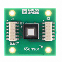
ADIS16209/PCBZ
Manufacturer Part Number
ADIS16209/PCBZ
Description
BOARD EVAL FOR ADIS16209
Manufacturer
Analog Devices Inc
Series
iMEMS®, iSensor™r
Specifications of ADIS16209/PCBZ
Sensor Type
Accelerometer, Inclinometer, 2 Axis
Sensing Range
±1.7g, ±90°
Interface
SPI Serial
Sensitivity
0.244mg/LSB, 0.025°/LSB
Voltage - Supply
3 V ~ 3.6 V
Embedded
No
Utilized Ic / Part
ADIS16209
Silicon Manufacturer
Analog Devices
Application Sub Type
Accelerometer - Dual-Axis
Kit Application Type
Sensing - Motion / Vibration / Shock
Silicon Core Number
ADIS16209
Kit Contents
Board
Lead Free Status / RoHS Status
Not applicable / RoHS compliant by exemption
For Use With
ADISUSBZ - KIT EVAL ADIS W/SOFTWARE USBADISEVALZ - KIT PC EVALUATION W/SOFTWARE
Lead Free Status / RoHS Status
Lead free / RoHS Compliant, Not applicable / RoHS compliant by exemption


BASIC OPERATION
The ADIS16209 requires only power/ground and SPI connec-
tions. The SPI is simple to hook up and is supported by many
common digital hardware platforms. Figure 20 provides a
simple hook-up diagram, while Table 2, Figure 2, and Figure 3
provide timing and bit assignments. Figure 4 provides the bit
sequence for accessing the register memory structure. Each
function within the ADIS16209 has its own 16-bit, 2-byte reg-
ister. Each byte has its own unique 6-bit address. Note that
all 16 SCLK cycles are required for the DIN bit sequence to
configure the output for the next data frame. The ADIS16209
supports full duplex mode operation. Table 6 provides the
entire user register map for the ADIS16209. For each register,
the lower bytes address is given. For those registers that have
two bytes, the upper bytes address is simply the lower bytes
address, incremented by 0x01.
Table 6. User Register Map
Name
ENDURANCE
SUPPLY_OUT
XACCL_OUT
YACCL_OUT
AUX_ADC
TEMP_OUT
XINCL_OUT
YINCL_OUT
ROT_OUT
XACCL_NULL
YACCL_NULL
XINCL_NULL
YINCL_NULL
ROT_NULL
ALM_MAG1
ALM_MAG2
ALM_SMPL1
ALM_SMPL2
ALM_CTRL
AUX_DAC
GPIO_CTRL
MSC_CTRL
SMPL_PRD
AVG_CNT
SLP_CNT
STATUS
COMMAND
R/W
R
R
R
R
R
R
R
R
R
R/W
R/W
R/W
R/W
R/W
R/W
R/W
R/W
R/W
R/W
R/W
R/W
R/W
R/W
R/W
W
R
W
Flash Backup
Yes
No
No
No
No
No
No
No
No
Yes
Yes
Yes
Yes
Yes
Yes
Yes
Yes
Yes
Yes
No
No
No
No
Yes
Yes
Yes
No
No
Address
0x00
0x12
0x14
0x16
0x18
0x1A
0x20
0x22
0x24
0x26
0x28
0x32
0x34
0x36
0x3C
0x3E
0x02
0x04
0x06
0x08
0x0A
0x0C
0x0E
0x10
0x1C to 0x1F
0x2A to 0x2F
0x30
0x38
0x3A
Size (Bytes)
2
2
2
2
2
2
2
2
2
2
2
2
2
2
2
2
2
2
2
2
2
2
2
2
2
2
4
6
2
Rev. B | Page 11 of 16
Many of the configuration registers have also been assigned
mirror locations in the flash memory, which effectively provide
them with a backup storage function. To ensure the backup of
these registers, the COMMAND register provides an initiation
bit for manual flash updates. The ENDURANCE register
provides a running count of these events.
Calibration, vertical rotation offset null
Function
Diagnostics, flash write counter (16-bit binary)
Output, power supply
Output, x-axis acceleration
Output, y-axis acceleration
Output, auxiliary ADC
Output, temperature
Output, ±90° x-axis inclination
Output, ±90° y-axis inclination
Output, ±180° vertical rotational position
Calibration, x-axis acceleration offset null
Calibration, y-axis acceleration offset null
Calibration, x-axis inclination offset null
Calibration, y-axis inclination offset null
Reserved, do not write to these locations
Alarm 1, amplitude threshold
Alarm 2, amplitude threshold
Alarm 1, sample period
Alarm 2, sample period
Alarm, source control register
Reserved
Auxiliary DAC data
Operation, digital I/O configuration and data
Operation, data-ready and self-test control
Operation, sample rate configuration
Operation, filter configuration
Operation, sleep mode control
Diagnostics, system status register
Operation, system command register
ADIS16209
Figure 20. Typical SPI Hook-up
DOUT
SCLK
DIN
CS
PF
SCK
MOSI
MISO
PROCESSOR/
EMBEDDED
DSP/FPGA
ADIS16209
Reference
Table 7
Table 7
Table 7
Table 7
Table 7
Table 7
Table 7
Table 7
Table 16
Table 16
Table 17
Table 17
Table 17
Table 18
Table 18
Table 19
Table 19
Table 20
Table 14
Table 13
Table 12
Table 8
Table 10
Table 9
Table 21
Table 15
Related parts for ADIS16209/PCBZ
Image
Part Number
Description
Manufacturer
Datasheet
Request
R

Part Number:
Description:
±1.7g Dual-Axis IMEMS Accelerometer Evaluation Board
Manufacturer:
Analog Devices Inc
Datasheet:

Part Number:
Description:
Inertial Sensor Evaluation System
Manufacturer:
Analog Devices Inc
Datasheet:
Part Number:
Description:
Manufacturer:
Analog Devices Inc
Datasheet:
Part Number:
Description:
Manufacturer:
Analog Devices Inc
Datasheet:
Part Number:
Description:
Manufacturer:
Analog Devices Inc
Datasheet:
Part Number:
Description:
Manufacturer:
Analog Devices Inc
Datasheet:
Part Number:
Description:
Manufacturer:
Analog Devices Inc
Datasheet:
Part Number:
Description:
Manufacturer:
Analog Devices Inc
Datasheet:
Part Number:
Description:
Manufacturer:
Analog Devices Inc
Datasheet:
Part Number:
Description:
Manufacturer:
Analog Devices Inc
Datasheet:
Part Number:
Description:
Manufacturer:
Analog Devices Inc
Datasheet:
Part Number:
Description:
Manufacturer:
Analog Devices Inc
Datasheet:
Part Number:
Description:
Manufacturer:
Analog Devices Inc
Datasheet: