ADIS16209/PCBZ Analog Devices Inc, ADIS16209/PCBZ Datasheet - Page 12
ADIS16209/PCBZ
Manufacturer Part Number
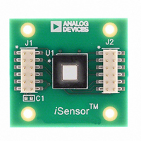
ADIS16209/PCBZ
Description
BOARD EVAL FOR ADIS16209
Manufacturer
Analog Devices Inc
Series
iMEMS®, iSensor™r
Specifications of ADIS16209/PCBZ
Sensor Type
Accelerometer, Inclinometer, 2 Axis
Sensing Range
±1.7g, ±90°
Interface
SPI Serial
Sensitivity
0.244mg/LSB, 0.025°/LSB
Voltage - Supply
3 V ~ 3.6 V
Embedded
No
Utilized Ic / Part
ADIS16209
Silicon Manufacturer
Analog Devices
Application Sub Type
Accelerometer - Dual-Axis
Kit Application Type
Sensing - Motion / Vibration / Shock
Silicon Core Number
ADIS16209
Kit Contents
Board
Lead Free Status / RoHS Status
Not applicable / RoHS compliant by exemption
For Use With
ADISUSBZ - KIT EVAL ADIS W/SOFTWARE USBADISEVALZ - KIT PC EVALUATION W/SOFTWARE
Lead Free Status / RoHS Status
Lead free / RoHS Compliant, Not applicable / RoHS compliant by exemption


ADIS16209
OUTPUT DATA REGISTERS
Table 7 provides the data configuration for each output data
register in the ADIS16209. Starting with the MSB of the upper
byte, each output data register has the following bit sequence:
new data (ND) flag, error/alarm (EA) flag, followed by 14 data
bits. The data bits are LSB justified, and in the case of the 12-bit
data formats, the remaining two bits are not used. The ND flag
indicates that unread data resides in the output data registers.
This flag clears and returns to 0 during an output register read
sequence. It returns to 1 after the next internal sample update
cycle completes. The EA flag indicates an error condition. The
STATUS register contains all of the error flags and provides the
ability to investigate the root cause.
Table 7. Output Data Register Formats
Register
SUPPLY_OUT
XACCL_OUT
YACCL_OUT
AUX_ADC
TEMP_OUT
XINCL_OUT
YINCL_OUT
ROT_OUT
1
2
3
OPERATION CONTROL REGISTERS
Internal Sample Rate
The SMPL_PRD register controls the ADIS16209 internal sample
rate and has two parts: a selectable time base and a multiplier. The
following relationship produces the sample rate:
Table 8. SMPL_PRD Bit Descriptions
Bit
15:8
7
6:0
An example calculation of the default sample period follows:
The sample rate setting has a direct impact on the SPI data
rate capability. For sample rates ≥546 SPS, the SPI SCLK can
run at a rate up to 2.5 MHz. For sample rates <546 SPS, the SPI
SCLK can run at a rate up to 1 MHz. The sample rate setting
also affects power dissipation. When the sample rate is set to
<546 SPS, power dissipation typically reduces by a factor
Scale denotes quantity per LSB.
Range is −90° to +90°.
Range is −179.975° to +180°.
t
SMPL_PRD = 0x01, B7 − B0 = 00000001
B7 = 0 → t
t
f
S
S
S
= 1∕t
= t
= t
Description
Not used
Time base (t
Increment setting (N
3
B
B
× N
× N
S
2
2
= 2731 SPS
B
S
S
+ 122.07 μs
= 244.14 μs, B6 … B0 = 000000001 → N
+ 122.07 μs = 244.14 × 1 + 122.07 = 366.21 μs
Bits
14
14
14
12
12
14
14
14
B
): 0 = 244.14 μs, 1 = 7.568 ms
Format
Binary, 3.3 V = 0x2A3D
Twos complement
Twos complement
Binary, 2 V = 0x0CCC
Binary, 25°C = 0x04FE
Twos complement
Twos complement
Twos complement
S
)
(Default = 0x0014)
Scale
0.30518 mV
0.24414 mg
0.24414 mg
0.6105 mV
−0.47°C
0.025°
0.025°
0.025°
S
= 1
1
Rev. B | Page 12 of 16
of 68%. The two different modes of operation offer a system-
level trade-off between performance (sample rate, serial transfer
rate) and power dissipation.
Power Management
In addition to offering two different performance modes for
power optimization, the ADIS16209 offers a programmable
shutdown period that the SLP_CNT register controls.
Table 9. SLP_CNT Bit Descriptions
Bit
15:8
7:0
For example, writing 0x08 to the SLP_CNT register places the
ADIS16209 into sleep mode for 4 sec. The only way to stop this
process is to remove power or reset the device.
Digital Filtering
The AVG_CNT register controls the moving average digital filter,
which determines the size of the moving average filter in eight
power-of-two step sizes (that is, 2
256). Filter setup requires one simple step: write the appropriate
M factor to the assigned bits in the AVG_CNT register.
Table 10. AVG_CNT Bit Descriptions
Bit
15:4
3:0
The following equation offers a frequency response relationship
for this filter:
H
–100
–20
–40
–60
–80
Description
Not used
Power-of-two step size, maximum binary value = 1000
A
20
0.001
0
(
Figure 21. Frequency Response—Moving Average Filter
Description
Not used
Data bits, 0.5 seconds/LSB
f
)
=
sin(
N
×
π
sin(
×
N
π
×
×
0.01
f
f
×
×
t
t
S
S
N = 128
)
)
f/f
M
S
= 1, 2, 4, 16, 32, 64, 128, and
N = 4
N = 16
(Default = 0x0000)
0.1
(Default = 0x0008)
Related parts for ADIS16209/PCBZ
Image
Part Number
Description
Manufacturer
Datasheet
Request
R

Part Number:
Description:
±1.7g Dual-Axis IMEMS Accelerometer Evaluation Board
Manufacturer:
Analog Devices Inc
Datasheet:

Part Number:
Description:
Inertial Sensor Evaluation System
Manufacturer:
Analog Devices Inc
Datasheet:
Part Number:
Description:
Manufacturer:
Analog Devices Inc
Datasheet:
Part Number:
Description:
Manufacturer:
Analog Devices Inc
Datasheet:
Part Number:
Description:
Manufacturer:
Analog Devices Inc
Datasheet:
Part Number:
Description:
Manufacturer:
Analog Devices Inc
Datasheet:
Part Number:
Description:
Manufacturer:
Analog Devices Inc
Datasheet:
Part Number:
Description:
Manufacturer:
Analog Devices Inc
Datasheet:
Part Number:
Description:
Manufacturer:
Analog Devices Inc
Datasheet:
Part Number:
Description:
Manufacturer:
Analog Devices Inc
Datasheet:
Part Number:
Description:
Manufacturer:
Analog Devices Inc
Datasheet:
Part Number:
Description:
Manufacturer:
Analog Devices Inc
Datasheet:
Part Number:
Description:
Manufacturer:
Analog Devices Inc
Datasheet: