HMR3500 DEMO Honeywell Microelectronics & Precision Sensors, HMR3500 DEMO Datasheet - Page 3
HMR3500 DEMO
Manufacturer Part Number
HMR3500 DEMO
Description
3-AXIS COMPASS MODULE DEMO KIT
Manufacturer
Honeywell Microelectronics & Precision Sensors
Series
TruePoint™r
Datasheet
1.HMR3500_DEMO.pdf
(6 pages)
Specifications of HMR3500 DEMO
Sensor Type
Magnetic, Digital Compass
Sensing Range
±0.7gauss
Interface
RS-232
Sensitivity
0.45 milligauss
Voltage - Supply
2.5 V ~ 5.2 V
Embedded
Yes, MCU, 16-Bit
Utilized Ic / Part
HMR3500
Silicon Manufacturer
Honeywell
Silicon Core Number
HMR3500
Kit Application Type
Sensing - Magnetic / Compass
Application Sub Type
Magnetic Sensor
Silicon Family Name
TruePoint
Lead Free Status / RoHS Status
Contains lead / RoHS non-compliant
Other names
342-1059


HMR3500
PIN CONFIGURATION
BASIC DEVICE OPERATION
The HMR3500 TruePoint™ Compass Module includes 3-axis Anisotropic Magneto-Resistive (AMR) sensors, 3-axis
MEMS accelerometers, a temperature sensor, and 16-bit microprocessor with onboard Analog to Digital Converter (ADC).
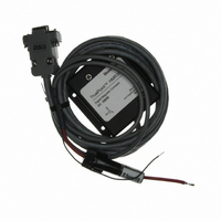
The HMR3500 is available as a printed circuit board assembly, or assembled in a black aluminum case with cable
assembly. Additionally, the cable assembly can be ordered separately. A demonstration kit of the HMR3500 is available
with the case, cable assembly, a CD of the CompassHost windows utility software for the user’s personal computer.
The HMR3500 requires an external DC power supply for the red (positive) and black (ground) wires of the cable
assembly. By feeding 5 volts at about 50 milli-amperes into the HMR3500, the compass will operate, and a red LED on
the printed circuit board assembly will begin blinking at a 1Hz rate. Lack of a blinking LED or at a rapid rate is an
indication of an error, and action should taken to cycle power on the compass electronics to reset the module.
As a factory default, the RS-232 interface is set at 9600 baud with one start bit, 8 data bits, one stop bit, and no parity bits.
The HMR3500 does not require any hardware or software handshaking or related features. The baud rate can be
changed by command after initial communication at the current baud rate.
The CompassHost utility software is a 32-bit Windows® application program that is provided with the HMR3500
demonstration kit, and can be used to evaluate the HMR3500’s performance and demonstrate the compass features. With
exception of the baud rate change command, the CompassHost is capable of sending and receiving all of the commands
of the compass/computer interface. Host computers should be capable of running Windows 9x, ME, NT, 2000, XP and
follow-on operating systems. An install program loads the executable file CompassHost.exe and ActiveX components. A
readme.txt file is also included to describe the installation process.
PHYSICAL CHARACTERISTICS
The circuit board for the HMR3500 is 1.57 by 1.97 by 0.52 inches and composed of multi-layer, fiberglass-epoxy printed
boards, with the main board horizontal and a vertical board for mounting the z-axis magnetic sensor and accelerometer.
The vertical board is held orthogonal to the main board by two brass hardware blocks to ensure mechanical orthogonality.
www.honeywell.com
Pin Number
1
2
3
4
5
Pin Name
Ground
Ground
RXD
TXD
+Vin
1.57
1.57
0.150
0.150
HMR3500 Top View and Dimensions
Power Supply Return and Ground Reference
RS-232 Receive Data
RS-232 Transmit Data
Positive Power Supply Voltage Input
Ground Reference (for twisted pair routing with +Vin)
1.65
1.65
1.97
1.97
Figure 1
Pin 1
Pin 1
0.170
0.170
1.00
1.00
0.150
0.150
Description
4 PLCS
4 PLCS
Y
Y
Direction
Direction
Forward
Forward
0.116
0.116
X
X
3
Related parts for HMR3500 DEMO
Image
Part Number
Description
Manufacturer
Datasheet
Request
R

Part Number:
Description:
Magnetic Sensor
Manufacturer:
Honeywell Microelectronics & Precision Sensors

Part Number:
Description:
MAGNETIC SENSORS
Manufacturer:
Honeywell Microelectronics & Precision Sensors

Part Number:
Description:
MAGNETIC SENSORS
Manufacturer:
Honeywell Microelectronics & Precision Sensors

Part Number:
Description:
MAGNETIC SENSORS
Manufacturer:
Honeywell Microelectronics & Precision Sensors
Part Number:
Description:
MAGNETIC SENSORS
Manufacturer:
Honeywell Microelectronics & Precision Sensors
Part Number:
Description:
MAGNETIC SENSORS
Manufacturer:
Honeywell Microelectronics & Precision Sensors
Datasheet:
Part Number:
Description:
MAGNETIC SENSORS
Manufacturer:
Honeywell Microelectronics & Precision Sensors

Part Number:
Description:
MAGNETIC SENSORS
Manufacturer:
Honeywell Microelectronics & Precision Sensors
Datasheet:

Part Number:
Description:
MAGNETIC SENSORS
Manufacturer:
Honeywell Microelectronics & Precision Sensors
Datasheet:

Part Number:
Description:
MAGNETIC SENSORS
Manufacturer:
Honeywell Microelectronics & Precision Sensors
Datasheet:

Part Number:
Description:
SENSOR LINEAR MAGN 1 AXIS 8-SIP
Manufacturer:
Honeywell Microelectronics & Precision Sensors
Datasheet:

Part Number:
Description:
SENSOR MAGN 2 AXIS 10-MSOP
Manufacturer:
Honeywell Microelectronics & Precision Sensors
Datasheet:

Part Number:
Description:
Magnetic Sensor
Manufacturer:
Honeywell Microelectronics & Precision Sensors
Datasheet:

Part Number:
Description:
Magnetic Sensor
Manufacturer:
Honeywell Microelectronics & Precision Sensors
Datasheet:

Part Number:
Description:
IC, MAGNETO RESISTIVE SENSOR, LCC-16
Manufacturer:
Honeywell Microelectronics & Precision Sensors
Datasheet: