ATQT600 Atmel, ATQT600 Datasheet - Page 33
ATQT600
Manufacturer Part Number
ATQT600
Description
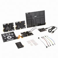
KIT EVAL TOUCH FOR QT600
Manufacturer
Atmel
Series
QTouch™r
Specifications of ATQT600
Sensor Type
Touch Screen
Interface
USB
Embedded
Yes, Other
Utilized Ic / Part
ATtiny88, ATmega324PA, ATxmega128A1
Processor To Be Evaluated
ATtiny88, ATmega324, ATxmega128
Data Bus Width
8 bit, 16 bit
Interface Type
USB
Maximum Operating Temperature
+ 85 C
Minimum Operating Temperature
- 40 C
Operating Supply Voltage
1.6 V to 3.6 V
Silicon Manufacturer
Atmel
Kit Application Type
Sensor
Application Sub Type
Touch Sensor
Kit Contents
USB Bridge, MCU Cards, Touchpad Cards
Svhc
No SVHC (15-Dec-2010)
Mcu Supported Families
ATtiny88,
Rohs Compliant
Yes
Lead Free Status / RoHS Status
Lead free / RoHS Compliant
Voltage - Supply
-
Sensitivity
-
Sensing Range
-
Lead Free Status / Rohs Status
Lead free / RoHS Compliant
Available stocks
Company
Part Number
Manufacturer
Quantity
Price
Company:

Part Number:
ATQT600
Manufacturer:
Atmel
Quantity:
135


4.1
4.2
4.2.1
Touch Sensors Design Guide
Introduction
Planar Construction
Introduction
This section describes how you design zero-dimensional sensors using a mutual-capacitance
implementation (see
implement keys for use with QMatrix sensor controllers.
As with a self-capacitance zero-dimensional type sensor, the guidelines for constructing a mutual-
capacitance sensor depend on whether the construction is planar or non-planar. The guidelines for these
two types of construction are discussed in the following sections.
With planar construction, both the electrodes and the traces for the sensor are fabricated on the same
plane of the insulating substrate (for example, a PCB or Flex PCB).
Field propagation relies heavily on the overlying panel as most of the coupling field flow is horizontal
(see
adhesive, and that air bubbles are avoided during lamination; bubbles that are too large or too numerous
can give rise to significant unit-to-unit variation.
Figure 4-1.
The X and Y electrodes are designed to optimize the distribution of the electric field that is coupling
through the overlying panel. This maximizes touch sensitivity, as the touching object (typically a finger)
has the maximum opportunity to disrupt this field coupling and cause a touch to be detected.
Figure
4-1). It is important to make sure that the sensor is firmly laminated to the panel with
Mutual-capacitance Zero-dimensional Sensors
Field Flow
Front
Panel
PCB
Section 1.2
Electrode (X)
and
Drive
Section
1.3). These styles of sensors are typically used to
Electrode (Y)
Receive
Adhesive
Section 4
10620D–AT42–04/09
4-1
Related parts for ATQT600
Image
Part Number
Description
Manufacturer
Datasheet
Request
R

Part Number:
Description:
DEV KIT FOR AVR/AVR32
Manufacturer:
Atmel
Datasheet:

Part Number:
Description:
INTERVAL AND WIPE/WASH WIPER CONTROL IC WITH DELAY
Manufacturer:
ATMEL Corporation
Datasheet:
Part Number:
Description:
Low-Voltage Voice-Switched IC for Hands-Free Operation
Manufacturer:
ATMEL Corporation
Datasheet:
Part Number:
Description:
MONOLITHIC INTEGRATED FEATUREPHONE CIRCUIT
Manufacturer:
ATMEL Corporation
Datasheet:
Part Number:
Description:
AM-FM Receiver IC U4255BM-M
Manufacturer:
ATMEL Corporation
Datasheet:
Part Number:
Description:
Monolithic Integrated Feature Phone Circuit
Manufacturer:
ATMEL Corporation
Datasheet:
Part Number:
Description:
Multistandard Video-IF and Quasi Parallel Sound Processing
Manufacturer:
ATMEL Corporation
Datasheet:
Part Number:
Description:
High-performance EE PLD
Manufacturer:
ATMEL Corporation
Datasheet:
Part Number:
Description:
8-bit Flash Microcontroller
Manufacturer:
ATMEL Corporation
Datasheet:
Part Number:
Description:
2-Wire Serial EEPROM
Manufacturer:
ATMEL Corporation
Datasheet: