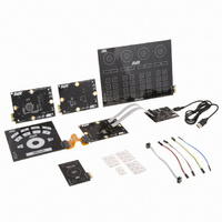
ATQT600 Atmel, ATQT600 Datasheet - Page 43

ATQT600
Manufacturer Part Number
ATQT600
Description
KIT EVAL TOUCH FOR QT600
Manufacturer
Atmel
Series
QTouch™r
Specifications of ATQT600
Sensor Type
Touch Screen
Interface
USB
Embedded
Yes, Other
Utilized Ic / Part
ATtiny88, ATmega324PA, ATxmega128A1
Processor To Be Evaluated
ATtiny88, ATmega324, ATxmega128
Data Bus Width
8 bit, 16 bit
Interface Type
USB
Maximum Operating Temperature
+ 85 C
Minimum Operating Temperature
- 40 C
Operating Supply Voltage
1.6 V to 3.6 V
Silicon Manufacturer
Atmel
Kit Application Type
Sensor
Application Sub Type
Touch Sensor
Kit Contents
USB Bridge, MCU Cards, Touchpad Cards
Svhc
No SVHC (15-Dec-2010)
Mcu Supported Families
ATtiny88,
Rohs Compliant
Yes
Lead Free Status / RoHS Status
Lead free / RoHS Compliant
Voltage - Supply
-
Sensitivity
-
Sensing Range
-
Lead Free Status / Rohs Status
Lead free / RoHS Compliant
Available stocks
Company
Part Number
Manufacturer
Quantity
Price
Company:
Part Number:
ATQT600
Manufacturer:
Atmel
Quantity:
135
Touch Sensors Design Guide
With the flooded-X two-layer method the X and Y electrodes are designed to overlap each other, with the
Y electrode nearest to touch. The X electrode must be separated some distance below the Y electrode
and be larger and of a solid fill (that is, flooded).
The Y electrode should be thin, typically between 0.1 mm and 0.5 mm, keeping in mind constraints
caused by electrode material resistance build-up, of course. The X electrode should be the same basic
shape as the Y electrode but bigger by around 2 mm on all sides.
The Y electrode can be more or less any shape – it can even be the outline shape of the key’s graphic,
which opens up some interesting possibilities for illumination. Just make sure that the largest open gaps
are not larger than 4 mm, or there will be dead spots in the key sensitivity for normal touch sizes. As a
guide, make the Y electrode a simple outline shape, such as a box, and then fill out the bounded region
with a grid of lines with a pitch of approximately 4 mm. Keys less than 4 x 4 mm are generally too small.
Ideally the X to Y layer separation should meet
Equation 4-7. X To Y Layer Separation
One important thing to realize is that the sensor does not suddenly stop working outside these limits. If
you make the ratio 5, for example, you can expect to get a lower SNR. This may or may not be
acceptable, depending on the system constraints. The SNR degrades approximately in proportion to this
ratio. If you make the ratio lower than 2, then one potential side effect is that the field coupling between X
and Y starts to rely more heavily on the overlying panel to propagate, and this can render the key more
sensitive to moisture effects
For example, with the stack shown in
Do not route any tracks in the region directly above the X flood – other than the Y electrode, of course.
Tracks can be placed directly behind the X flood so long as those signals are not excessively noisy
Y traces connecting the Y electrode can use a via and escape down and away underneath the X flood.
Alternatively, the trace can simply exit on the same layer as the electrode itself, routed directly away
from any nearby X regions or traces.
1. QMatrix measurements have the useful property that placing an isolated water drop so that it couples between
2. There are no hard rules on this. Proceed with caution and expect some iteration in your design process if you
and X and Y, actually increases the coupling; the opposite to a normal touch. This is known as anti-touch. As a
result, QMatrix has a natural moisture rejecting property. However, if the overlying panel plays a significant role in
the coupling between X and Y, introducing a water bead will have a proptionately larger anti-touch effect. If this
anti-touch is compensated for by the controller chip (either over some period of time or immediately with a
calibrate command) and then the anti-touch is removed ( perhaps by wiping the panel), the sensor will jump
towards touch and can cause a stuck key. It is therefore desirable to reduce the moisture sensitivity by controlling
the stack as outlined.
route highly active signals behind the X flood.
S
2 ( S
where:
S
TouchToXStack
YToXStack
S is the sensitivity factor for the various material stacks, as defined in
Section 2.3.3 “Front Panel Materials” on page
YtoXStack
=
(1)
.
/ S
r
=
2
------------------------ -
t
TouchToXStack
2
----- -
t
1
r
1
1
+
Figure 4-10 on page
----- -
t
2
r
2
) 12
Equation
Mutual-capacitance Zero-dimensional Sensors
4-7.
4-10:
2-5.
10620D–AT42–04/09
4-11
(2)
.


