STM8L-DISCOVERY STMicroelectronics, STM8L-DISCOVERY Datasheet
STM8L-DISCOVERY
Specifications of STM8L-DISCOVERY
Available stocks


Related parts for STM8L-DISCOVERY


STM8L-DISCOVERY Summary of contents
Page 1
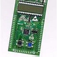
... Introduction The STM8L-DISCOVERY helps you to discover the STM8L ultralow power features and to develop and share your applications based on an STM8L152C6T6 and includes an ST- Link embedded debug tool interface, LCD (24 segments, 4 commons), LEDs and push buttons. Figure 1. STM8L-DISCOVERY board September 2010 STM8L-DISCOVERY ...
Page 2
... System requirements . . . . . . . . . . . . . . . . . . . . . . . . . . . . . . . . . . . . . . . . . 3 1.3 Development toolchain . . . . . . . . . . . . . . . . . . . . . . . . . . . . . . . . . . . . . . . . 4 1.4 Demonstration software . . . . . . . . . . . . . . . . . . . . . . . . . . . . . . . . . . . . . . . 4 1.5 Order code . . . . . . . . . . . . . . . . . . . . . . . . . . . . . . . . . . . . . . . . . . . . . . . . . 4 2 Features . . . . . . . . . . . . . . . . . . . . . . . . . . . . . . . . . . . . . . . . . . . . . . . . . . . 5 3 Hardware and layout . . . . . . . . . . . . . . . . . . . . . . . . . . . . . . . . . . . . . . . . . 6 3.1 STM8L152C6T6 microcontroller . . . . . . . . . . . . . . . . . . . . . . . . . . . . . . . . 9 3.2 Embedded ST-Link . . . . . . . . . . . . . . . . . . . . . . . . . . . . . . . . . . . . . . . . . . 11 3.2.1 3.2.2 3.3 Power supply and power selection . . . . . . . . . . . . . . . . . . . . . . . . . . . . . . 13 3.4 LEDs . . . . . . . . . . . . . . . . . . . . . . . . . . . . . . . . . . . . . . . . . . . . . . . . . . . . 13 3.5 Push buttons . . . . . . . . . . . . . . . . . . . . . . . . . . . . . . . . . . . . . . . . . . . . . . 13 3.6 Built-in IDD measurement circuit . . . . . . . . . . . . . . . . . . . . . . . . . . . . . . . 14 3 ...
Page 3
... Getting started 1. Check jumper positions on the board, JP1 and CN3 ON (Discovery selected). 2. Connect the STM8L-DISCOVERY board with a USB cable to power the board. Red LED LD2 (PWR) then lights up. 3. Function 1 is executed and each click on user button B2 changes the executed function as described in Table 1 ...
Page 4
... LCD the consumption of the MCU in run and low power modes. The latest versions of this demonstration source code and associated documentation can be downloaded from www.st.com/stm8l-discovery. 1.5 Order code To order the STM8L ultralow power Discovery, use the order code STM8L-DISCOVERY. 4/29 Doc ID 17693 Rev 1 UM0970 ...
Page 5
... UM0970 2 Features The STM8L-DISCOVERY offers the following features: ● STM8L152C6T6 microcontroller Flash RAM EEPROM in 48-pin LQFP ● On-board ST-Link with selection mode switch to use the kit as a stand-alone ST-Link (with SWIM connector for programming and debugging) ● Two red LEDs; LD1 for USB communication, LD2 for 3.3 V power on ● ...
Page 6
... Hardware and layout 3 Hardware and layout The STM8L-DISCOVERY is designed around the STM8L152C6T6 microcontroller in a 48- pin LQFP package. Figure 2 illustrates the connections between the STM8L152C6T6 and its peripherals (ST- Link, push button, LED, LCD and connectors). Figure 3 and Figure 4 Figure 2. Hardware block diagram 6/29 help you to locate these features on the STM8L-DISCOVERY ...
Page 7
... Figure 3. Top layout D1 diode LD1 COM CN2 SWIM connector LCD 24 segments JP1 I measurement DD +3.3V power supply input SB1,2 X2 crystal STM8L152C6T6 B1 Reset button LD3 LED green Doc ID 17693 Rev 1 Hardware and layout D2 diode LD2 power ST-Link CN3 ST-Link/Discovery selector IDD module +5V power supply ...
Page 8
Hardware and layout Figure 4. Bottom layout SB3,5,7,9 PRG-32 (RESERVED) SB4,6,8,10 DEFAULT SB11,12,14 IDD_Measurement SB13,15 X3 crystal SB17 B2-USER SB16 B1-RESET 8/29 Doc ID 17693 Rev 1 UM0970 P2 connector P1 connector JP1 IDD P3 connector ...
Page 9
... Fast switching from Static and Dynamic power modes ● Analog functional down to 1.8 V, programming down to 1.65 V: Full functionality over the complete V For more information see the STM8L152C6T6 datasheet (Doc ID 15962) on the ST website. The STM8L152C6T6 8-bit microcontroller offers: 32 Kbytes of Flash memory 2 Kbytes RAM ...
Page 10
... Hardware and layout Figure 6. STM8L152C6T6 block diagram 10/29 Doc ID 17693 Rev 1 UM0970 ...
Page 11
... UM0970 3.2 Embedded ST-Link The ST-Link programming and debugging tool is integrated on the STM8L-DISCOVERY. The embedded ST-Link can be used in 2 different ways according to the jumper states (see Table 2): ● to program/debug the MCU on board, ● to program/debug an MCU in an external application board using a cable connected to SWIM connector CN2 ...
Page 12
... Using the ST-Link to program/debug the STM8L on board To program the STM8L on board, simply plug in the two jumpers on CN3, as shown in Figure 8 in red, but do not use the CN2 connector as that could disturb communication with the STM8L152C6T6 of the STM8L-DISCOVERY. Figure 8. STM8L-DISCOVERY connections image 3.2.2 Using the ST-Link to program/debug an external STM8L application It is very easy to use the ST-Link to program the STM8L on an external application ...
Page 13
... LD1 COM: Red LED indicates communication in progress between PC and ST-Link. ● LD2 PWR: Red LED indicates that the board is powered. ● LD3 PE7: Green LED is a user LED connected to the I/O PE7 of the STM8L152C6T6. ● LD4 PC7: Blue LED is a user LED connected to the I/O PC7 of the STM8L152C6T6. 3.5 Push buttons ● ...
Page 14
... JP1 pin 1 and pin 2. For I measurement by the MCU itself, the circuit below is implemented on the STM8L- DD DISCOVERY. Solder bridges SB11, SB12 and SB14 must be closed and a jumper must be plugged between JP1 pin 2 and pin 3. Figure 10. STM8L-DISCOVERY I IDD VDD_MCU off on U4 ...
Page 15
... R21 is shorted, the IDD measurement is stored in C11, and the MCU is woken up. After wakeup the MCU can measure the IDD current corresponding to the Low power mode stored in C11. Figure 11. STM8L-DISCOVERY I The Low power mode measurement procedure can be used in Halt or Active halt mode if the I ...
Page 16
... PC1 is only connected to P2 SB17 (B2-USER) On PC1 is connected to P2 and push button B2 for user 1. Default state is in bold type. 16/29 current (typical Ibias is ~240 nA). To obtain a reliable STM8L152 I . The Ibias measurement procedure is part of the DD measurement performed in Low power mode. DD Doc ID 17693 Rev 1 low power ...
Page 17
... UM0970 3.8 LCD (24 segments, 4 commons) This LCD allows the STM8L152C6T6 to display any information on six 14-segment digits and 4 BARs, using all COMs. (See the LCD segment mapping in connections in Table Note: This LCD also supports six 8-segment digits by only using COM0 and COM1. ...
Page 18
... Hardware and layout Table 5. LCD connections STM8L152C6T6 Pin name PA7_LCDSEG0 PE0_LCDSEG1 PE1_LCDSEG2 PE2_LCDSEG3 PE3_LCDSEG4 PE4_LCDSEG5 PE5_LCDSEG6 PD0_LCDSEG7 PD2_LCDSEG8 PD3_LCDSEG9 PB0_LCDSEG10 PB1_LCDSEG11 PD1_LCDCOM3 PA6_LCDCOM2 PA5_LCDCOM1 PA4_LCDCOM0 PB2_LCDSEG12 PB3_LCDSEG13 PB4_LCDSEG14 PB5_LCDSEG15 PB6_LCDSEG16 PB7_LCDSEG17 PD4_LCDSEG18 PD5_LCDSEG19 PD6_LCDSEG20 PD7_LCDSEG21 PC2_LCDSEG22 PC3_LCDSEG23 18/29 Pin COM3 COM2 ...
Page 19
... Extension connection 4 Extension connection Male headers P1, P2 and P3 can connect the STM8L-DISCOVERY to a standard prototyping/wrapping board. All GPI/Os of STM8L152C6T6 are available on it. P1, P2 and P3 can also be probed by an oscilloscope, logical analyzer or voltmeter. Table 6. P1 pinout Pin number Pin number (P1) (STM8L 19/29 ...
Page 20
... UM0970 Table 6. P1 pinout (continued) Pin number Pin number (P1) (STM8L Table 7. P2 pinout Pin number Pin number (P2) (STM8L Board pin Main name function 19 PE5 I/O Port E5 20 PD0 I/O Port D0 21 PD1 I/O Port D1 9/40 GND Main Pin name function +5V NC ...
Page 21
... UM0970 Table 7. P2 pinout (continued) Pin number Pin number (P2) (STM8L Main Pin name function 42 PC3 I/O Port C3 41 PC2 I/O Port C2 38 PC1 I/O Port C1 37 PC0 I/O Port C0 36 PD7 I/O Port D7 35 PD6 I/O Port D6 34 PD5 I/O Port D5 ...
Page 22
... Extension connection Table 8. P3 pinout Pin number Pin number (P3) (STM8L 22/29 Main Pin name function 22 PD2 I/O Port D2 23 PD3 I/O Port D3 24 PB0 I/O Port B0 25 PB1 I/O Port B1 26 PB2 I/O Port B2 27 PB3 I/O Port B3 28 PB4 I/O Port B4 ...
Page 23
... Electrical schematics Figure 13. STM8L-DISCOVERY IDD_CNT_EN IDD_Measurement IDD_WAKEUP PA[0..7] PB[0..7] PC[0..7] PD[0..7] PE[0..7] PF0 RESET# ST_LINK_SWIM P1 EXT_3V3 1 PA0 IDD_CNT_EN 2 IDD_Measurement 3 RST PA1 IDD_WAKEUP 4 PA2 5 PA3 6 PA4 7 PA5 8 PA6 9 PA7 10 PE0 11 PE1 12 PE2 13 PE3 14 PE4 15 PE5 16 PD0 17 PD1 18 19 Header 19 ST_LINK.SCHDOC IDD_measurement.SchDoc U_ST_LINK ...
Page 24
... PD4_LCDSEG18 PD5_LCDSEG19 PD6_LCDSEG20 PD7_LCDSEG21 PC2_LCDSEG22 PC3_LCDSEG23 PA7_LCDSEG0 PE0_LCDSEG1 PE1_LCDSEG2 PE2_LCDSEG3 PE3_LCDSEG4 PE4_LCDSEG5 PE5_LCDSEG6 LCD PB6_LCDSEG16 PB5_LCDSEG15 PB4_LCDSEG14 PB3_LCDSEG13 PB2_LCDSEG12 PA4_LCDCOM0 PA5_LCDCOM1 U5 GH08172T PA6_LCDCOM2 PD1_LCDCOM3 PB1_LCDSEG11 PB0_LCDSEG10 PD3_LCDSEG9 PD2_LCDSEG8 PD0_LCDSEG7 STMicroelectronics Title: Number: STM8L-DISCOVERY LCD MB915 B.2(SCH.PCB) Date: 7/15/2010 2 5 Rev: Sheet of ...
Page 25
... Q13 Q10 R26 3 14 Q14 Q8 10K CLR GND CO C13 R22 R23 M74HC4060TTR 1nF 15K 30K Oscillator frequency 30KHz PF0 IDD_Measurement SB11 PE6 IDD_WAKEUP SB12 R19 47K PC4 IDD_CNT_EN SB14 STMicroelectronics Title: STM8L-DISCOVERY IDD_Measurement MB915 B.2(SCH.PCB) Date: 7/15/2010 Number: Rev: 3 Sheet ...
Page 26
... IDD_CNT_EN PC3_LCDSEG23 User Button PC2_LCDSEG22 VDD_MCU User_PB SB17 PD7_LCDSEG21 PD6_LCDSEG20 PD5_LCDSEG19 USER (Blue) PD4_LCDSEG18 IDD_Measurement PB7_LCDSEG17 PB6_LCDSEG16 PB5_LCDSEG15 PB4_LCDSEG14 PB3_LCDSEG13 PB2_LCDSEG12 PB1_LCDSEG11 STMicroelectronics Title: STM8L-DISCOVERY MCU MB915 B.2(PCB.SCH) Date: 7/15/2010 Number: Rev: +3V3 R30 4K7 B2 C25 100nF SWIM LED 4 5 Sheet of ...
Page 27
... Jumpers OFF --> ST-LINK Selected R8 ST_LINK_LED 510 U1 D1 +5V LD1117S33TR BAT60JFILM Vin Vout 10uF 10uF 100nF +3V3 EXT_3V3 STMicroelectronics Title: STM8L-DISCOVERY ST-LINK (SWIM only) MB915 B.2(PCB.SCH) Date: 7/15/2010 Number: Rev: ST_LINK_SWIM RESET# +3V3 SWCLK SWDIO COM LD1 RED PWR LD2 RED 5 5 Sheet of ...
Page 28
Revision history 6 Revision history Table 9. Document revision history Date 24-Sep-2010 28/29 Revision 1 Initial release. Doc ID 17693 Rev 1 UM0970 Changes ...
Page 29
... UM0970 Information in this document is provided solely in connection with ST products. STMicroelectronics NV and its subsidiaries (“ST”) reserve the right to make changes, corrections, modifications or improvements, to this document, and the products and services described herein at any time, without notice. All ST products are sold pursuant to ST’s terms and conditions of sale. ...