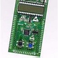
STM8L-DISCOVERY STMicroelectronics, STM8L-DISCOVERY Datasheet - Page 16

STM8L-DISCOVERY
Manufacturer Part Number
STM8L-DISCOVERY
Description
BOARD EVALUATION STM8L15X
Manufacturer
STMicroelectronics
Series
STM8L EnergyLiter
Type
MCUr
Specifications of STM8L-DISCOVERY
New! Us2012 Catalog Page
STM8L-Discovery_STM32L152-EVAL
Contents
Board
Processor To Be Evaluated
STM8L15X
Processor Series
STM8
Data Bus Width
8 bit
Interface Type
USART, I2C, SPI
Core
ARM
Dimensions
7 mm x 7 mm
Operating Supply Voltage
3.3 V to 5 V
Silicon Manufacturer
ST Micro
Core Architecture
STM8
Core Sub-architecture
STM8
Silicon Core Number
STM8
Silicon Family Name
STM8L1xx
For Use With/related Products
STM8L15x
Lead Free Status / RoHS Status
Lead free / RoHS Compliant
Other names
497-10660
Available stocks
Company
Part Number
Manufacturer
Quantity
Price
Company:
Part Number:
STM8L-DISCOVERY
Manufacturer:
STMicroelectronics
Quantity:
65
Hardware and layout
3.6.4
3.7
Table 4.
1. Default state is in bold type.
16/29
SB1,2
(X2 crystal)
SB3,5,7,9
(DEFAULT)
SB4,6,8,10
(PRG-32)
SB11,12,14
(IDD_Measurement)
SB13,15
(X3 crystal)
SB16
(B1-RESET)
SB17
(B2-USER)
Bridge
Ibias current measurement procedure
In Low power mode the bias current of operational amplifier input (U4 pin 4) is not negligible
compared to I
measurement it is mandatory to subtract the bias current from the I
measurement since this current is not sinked by the MCU. Ibias is measured during
production test and stored in the MCU EPROM. The demonstration software, Discover, uses
this value to display the correct I
demonstration software and can be launched if required.
The procedure for Ibias measurement (implemented in the Demo) is:
1.
2.
3.
4.
5.
6.
Solder bridges
Solder bridge
Power off the board (disconnect the USB cable).
Set jumper JP1 to OFF position (pins 1 and 2).
Push down B2 (USER button), power on the board from the USB.
Wait at least 1 second before releasing B2, the LCD displays the Ibias measurement.
Power off the board (disconnect the USB cable).
Set jumper JP1 to ON position (pins 2 and 3). The Ibias value is now stored. The bias
current is then subtracted from the I
Off
On
On
Off
Off
On
Off
On
Off
On
Off
On
State
(1)
DD
PA2, PA3 are disconnected from P1
X2, C19, C20 and R24 provide a clock as shown in schematics
PA2, PA3 are connected to P1 (X2, C19, C20, R24 must not be fitted)
Reserved, do not modify
Reserved, do not modify
PFO, PE6, PC4 are available and IDD module cannot be used
JP1 must be set to OFF
PFO, PE6, PC4 are used by IDD module
JP1 must be set to ON
PC5, PC6 are only connected to P2 (but do not remove X3, C21, C23, R27)
PC5, PC6 are connected to P2. X3, C21, C23 and R27 provide 32 KHz clock
PA1/RESET signal is only connected to P1
PA1/RESET signal is used by ST_LINK as SWIM_RST and also connected to P1
PC1 is only connected to P2
PC1 is connected to P2 and push button B2 for user
current (typical Ibias is ~240 nA). To obtain a reliable STM8L152 I
Doc ID 17693 Rev 1
DD
. The Ibias measurement procedure is part of the
DD
measurement performed in Low power mode.
Description
DD
low power
DD
UM0970


