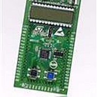
STM8L-DISCOVERY STMicroelectronics, STM8L-DISCOVERY Datasheet - Page 14

STM8L-DISCOVERY
Manufacturer Part Number
STM8L-DISCOVERY
Description
BOARD EVALUATION STM8L15X
Manufacturer
STMicroelectronics
Series
STM8L EnergyLiter
Type
MCUr
Specifications of STM8L-DISCOVERY
New! Us2012 Catalog Page
STM8L-Discovery_STM32L152-EVAL
Contents
Board
Processor To Be Evaluated
STM8L15X
Processor Series
STM8
Data Bus Width
8 bit
Interface Type
USART, I2C, SPI
Core
ARM
Dimensions
7 mm x 7 mm
Operating Supply Voltage
3.3 V to 5 V
Silicon Manufacturer
ST Micro
Core Architecture
STM8
Core Sub-architecture
STM8
Silicon Core Number
STM8
Silicon Family Name
STM8L1xx
For Use With/related Products
STM8L15x
Lead Free Status / RoHS Status
Lead free / RoHS Compliant
Other names
497-10660
Available stocks
Company
Part Number
Manufacturer
Quantity
Price
Company:
Part Number:
STM8L-DISCOVERY
Manufacturer:
STMicroelectronics
Quantity:
65
Hardware and layout
3.6
Note:
Figure 10. STM8L-DISCOVERY I
3.6.1
3.6.2
14/29
+3V3
off
VDD_MCU
IDD
R20
2(1%)
on
JP1
S
Built-in IDD measurement circuit
The STM8L-DISCOVERY built-in I
STM8L152C6T6 to be measured and displayed on the LCD Glass while the MCU is in Run
or Low power saving modes.
●
●
When jumper JP1 is removed the current consumption of the STM8L152C6T6 can be
measured by connecting an ammeter between jumper JP1 pin 1 and pin 2.
For I
DISCOVERY. Solder bridges SB11, SB12 and SB14 must be closed and a jumper must be
plugged between JP1 pin 2 and pin 3.
R21
2K(1%)
Run mode
In Run mode, I
connected to the 2Ω shunt resistor (R20). In this case IDD_CNT_EN remains high during
measurement, so R21 remains in short-circuit during the measurement because of transitor
T1 which remains ON permanently. The jumper JP1 must be connected between pins 2 and
3 of JP1.
Low power mode
In Low power modes (Halt or Active halt), the operational amplifier MAX9938FEUK+ (U4) is
connected to the 2KΩ shunt resistor (R21), controlled by the analogue switch STT5PF20V
(T1). In this case the counter 74HC4060 (U3) enabled by IDD_CNT_EN manages the
measurement timing according to
G
D
T1
STT5PF20V
DD
JP1 in ON position: STM8L152C6T6 is powered through I
(default).
JP1 in OFF position: STM8L152C6T6 is powered directly by +3V3, I
circuit is bypassed.
measurement by the MCU itself, the circuit below is implemented on the STM8L-
5
4
+3V3
U4
MAX9938FEUK+
DD
3
5
current is measured using the operational amplifier MAX9938FEUK+ (U4)
U7
74LX1G04CTR
3
DD
1
4
3
U6
74H1G66STR
I/O
C
GND
measurement circuit
VCC
O/I
Doc ID 17693 Rev 1
2
5
Figure
DD
1
2
3
4
5
6
7
8
+3V3
measurement circuit allows the consumption of the
U3
M74HC4060TTR
Q12
Q13
Q14
Q6
Q5
Q7
Q4
GND
11.
VCC
CLR
Q10
R18
10K
CO
CO
Q8
Q9
CI
16
15
14
13
12
11
10
9
+3V3
C11
1uF
Oscillator frequency 30KHz
C13
1nF
3
R17
0
C12
100nF
T2
STT5PF20V
R22
15K
R23
30K
4
5
1
2
6
+3V3
R26
10K
+3V3
DD
measurement circuit
R19
47K
SB11
SB12
SB14
DD
measurement
PF0
PE6
PC4
IDD_CNT_EN
IDD_Measurement
IDD_WAKEUP
UM0970


