EDK2398 Renesas Electronics America, EDK2398 Datasheet - Page 12
EDK2398
Manufacturer Part Number
EDK2398
Description
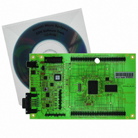
DEV EVALUATION KIT H8S/2398
Manufacturer
Renesas Electronics America
Series
H8®r
Type
MCUr
Specifications of EDK2398
Contents
2G (Second-generation) Evaluation Board, HEW debugger support, Cable and CD-ROM
For Use With/related Products
H8S/2398
Lead Free Status / RoHS Status
Contains lead / RoHS non-compliant


5.6. E10A H
E10A/E10T is not supported on the EDK2398
5.7. B
The method for placing the microcontroller device in to Boot mode for reprogramming has been incorporated into a complex
programmable logic device (CPLD). This is not necessary for most user designs but allows a measure of increased flexibility
for the EDK designs. Mode transitions including boot mode transitions only require the reset to be held active while the mode
settings are presented. On releasing reset the microcontroller will be in the required mode.
The logic design detects a power up event and provides a timed reset pulse to guarantee the reset of the device. At the end
of the rest pulse the processor will be placed in user mode and any code in the device will execute.
During user mode the NMI button can be pressed at any time. This will provide a single de-bounced NMI interrupt to the
device.
Pressing the boot button will cause the boot mode controller to reset the device and, during the reset period, present the
required mode settings to start the device in boot mode. At the end of the reset period the boot mode settings will have been
latched into the device which will then be ready to accept a boot mode connection via the RS232 interface or the flash
programming header. Pressing the boot button during a normal reset will not cause the EDK to enter boot mode.
The boot mode settings are fixed at mode 0. The required mode settings are made using a tri-state capable buffer.
Note:
5.7.1. CPLD C
The code is based upon a four state machine providing a guaranteed reset period which can be extended by holding the
relevant control input in the active state. When released the timer will extend the reset for approximately 500mS.
The states are split into two functions, one for User mode and one for Boot mode. The first state of each is used to hold the
reset line active. When the timer expires then the second state is used to hold the device in the selected mode and wait for
an external control signal to either move back into the user reset state or into the boot reset state.
5.7.2. S
TATE
OOT
The boot control device is programmed to support all possible EDK products.
For this reason the reset pulse is over 500ms. Repetitive activation of either the Boot or Reset buttons will restart
the reset timer and extend the reset period. Pressing the boot button within the 500mS period of a reset will not
cause the board to enter boot mode.
C
D
ONTROL
EADER
IAGRAM
ODE
Async
/Res
Waiting
Reset
ResSw . /Res
Boot Mode Controller : Positive Logic
F
IGURE
Res
(BootSW + ResSw + CTS)
/Res . Reset
5-2: CPLD S
. /Res
(CTS+BootSw) . /Res
Reset Timer
TATE
D
IAGRAM
Clocked Transitions
(All solid transition
/Res . Boot
using NE555
lines)
BootWaiting
Res
/Res
Boot
12
Related parts for EDK2398
Image
Part Number
Description
Manufacturer
Datasheet
Request
R

Part Number:
Description:
KIT STARTER FOR M16C/29
Manufacturer:
Renesas Electronics America
Datasheet:

Part Number:
Description:
KIT STARTER FOR R8C/2D
Manufacturer:
Renesas Electronics America
Datasheet:

Part Number:
Description:
R0K33062P STARTER KIT
Manufacturer:
Renesas Electronics America
Datasheet:

Part Number:
Description:
KIT STARTER FOR R8C/23 E8A
Manufacturer:
Renesas Electronics America
Datasheet:

Part Number:
Description:
KIT STARTER FOR R8C/25
Manufacturer:
Renesas Electronics America
Datasheet:

Part Number:
Description:
KIT STARTER H8S2456 SHARPE DSPLY
Manufacturer:
Renesas Electronics America
Datasheet:

Part Number:
Description:
KIT STARTER FOR R8C38C
Manufacturer:
Renesas Electronics America
Datasheet:

Part Number:
Description:
KIT STARTER FOR R8C35C
Manufacturer:
Renesas Electronics America
Datasheet:

Part Number:
Description:
KIT STARTER FOR R8CL3AC+LCD APPS
Manufacturer:
Renesas Electronics America
Datasheet:
Part Number:
Description:
KIT STARTER FOR RX610
Manufacturer:
Renesas Electronics America
Datasheet:

Part Number:
Description:
KIT STARTER FOR R32C/118
Manufacturer:
Renesas Electronics America
Datasheet:

Part Number:
Description:
KIT DEV RSK-R8C/26-29
Manufacturer:
Renesas Electronics America
Datasheet:

Part Number:
Description:
KIT STARTER FOR SH7124
Manufacturer:
Renesas Electronics America
Datasheet:

Part Number:
Description:
KIT STARTER FOR H8SX/1622
Manufacturer:
Renesas Electronics America
Datasheet:

Part Number:
Description:
KIT DEV FOR SH7203
Manufacturer:
Renesas Electronics America
Datasheet: