DM300004-1 Microchip Technology, DM300004-1 Datasheet - Page 92
DM300004-1
Manufacturer Part Number
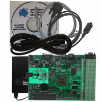
DM300004-1
Description
BOARD DEMO DSPICDEM.NET 1
Manufacturer
Microchip Technology
Series
dsPIC™r
Type
Microcontrollerr
Specifications of DM300004-1
Contents
*
Mcu Supported Families
DsPIC30F
Supported Devices
DsPIC30F6014
For Use With
PIC30F5013
Lead Free Status / RoHS Status
Lead free / RoHS Compliant
For Use With/related Products
FCC/JATE PSTN, Ethernet NIC
Lead Free Status / RoHS Status
na, Lead free / RoHS Compliant
Other names
DM300004-1R
DM300004-1R
DM300004-1R


PICDEM.net™ 1 and dsPICDEM.net 2 Connectivity Dev Board User’s Guide
DS51471A-page 88
7.1.1
A single RS-232 serial communication channel is provided on the dsPICDEM.net
Development Board. This serial communication channel, labeled J5, can be configured
as an RS-232 or RS-485/RS-422 communication channel via jumpers J17, J18 and
J19. The following jumper connections are required for RS-232 serial communications:
• J19, shunt pins 1-2 for Tx channel support
• J19, shunt pins 3-4 for Rx channel support
• J17, shunt pins 1-2 for Request-to-Send (RTS) support
• J17, shunt pins 3-4 for Clear-to-Send (CTS) support
• J18, shunt pins 2-3 for Rx connection to the dsPIC device
Jumper 19 connects the dsPIC UART channel 1 U1RX and U1TX pins to an RS-232
level shifting IC, U7. The serial port is configured as DCE, and can be connected to a
PC using a straight-through cable. If hardware handshaking is required, inserting
shunts on jumper J17 will connect CTS and RTS to port pins RA9 and RA10 on the
dsPIC device. These pins can support CTS/RTS through a bit-bang control approach.
Both pins are connected to IC U7.
7.1.2
The CAN RXD and TXD lines of the MCP2551 are connected to the dsPIC CANRX and
CANTX pins. CAN bus signals, CANH and CANL, are available on the DB9 connector
J4. The CANH and CANL bus can be locally terminated with a 120 ohm by inserting
jumper, J3.
7.1.3
Signals for the RS-485/RS-422 port are available on the 6-pin terminal block labeled
TB1. The terminal block is configurable from RS-485 to RS-422 by removing the
jumper on J2. Inserting jumper J1 will terminate the bus with a 120 ohm resistor.
The RX485 and TX485 lines of the MAX489E can be tied to the dsPIC UART channel 1
U1RX and U1TX pins by the following jumper settings:
• J19, shunt pins 1-2 for Tx channel support
• J19, shunt pins 3-4 for Rx channel support
• J18, shunt pins 1-2 for Rx connection to the dsPIC device
MAX489E receiver and driver output enables are controlled by port pins RG0 and RG1,
respectively.
7.1.4
This is a -40°C to +125°C linear output temperature sensor (TC1047A) connected to
analog channel AN3 of the dsPIC device. The output of the temperature sensor, U2, is
fed through a second order low-pass filter before connection to the dsPIC device. The
LP filter cutoff frequency is set at 10 Hz. The output voltage range for the TC1047A is
typically 750 mV at +25°C. The TC1047A exhibits a typical 10 mV/C voltage slope.
Note: The shunts for J17 and J19 must be connected vertically.
Note: The shunts for J19 must be connected vertically.
RS-232 Serial Port
CAN Port
RS-485/RS-422 Port
Temperature Sensor
2004 Microchip Technology Inc.
Related parts for DM300004-1
Image
Part Number
Description
Manufacturer
Datasheet
Request
R

Part Number:
Description:
Manufacturer:
Microchip Technology Inc.
Datasheet:
Part Number:
Description:
Manufacturer:
Microchip Technology Inc.
Datasheet:
Part Number:
Description:
Manufacturer:
Microchip Technology Inc.
Datasheet:
Part Number:
Description:
Manufacturer:
Microchip Technology Inc.
Datasheet:
Part Number:
Description:
Manufacturer:
Microchip Technology Inc.
Datasheet:
Part Number:
Description:
Manufacturer:
Microchip Technology Inc.
Datasheet:
Part Number:
Description:
Manufacturer:
Microchip Technology Inc.
Datasheet:
Part Number:
Description:
Manufacturer:
Microchip Technology Inc.
Datasheet: