DM300004-1 Microchip Technology, DM300004-1 Datasheet - Page 95
DM300004-1
Manufacturer Part Number
DM300004-1
Description
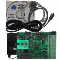
BOARD DEMO DSPICDEM.NET 1
Manufacturer
Microchip Technology
Series
dsPIC™r
Type
Microcontrollerr
Specifications of DM300004-1
Contents
*
Mcu Supported Families
DsPIC30F
Supported Devices
DsPIC30F6014
For Use With
PIC30F5013
Lead Free Status / RoHS Status
Lead free / RoHS Compliant
For Use With/related Products
FCC/JATE PSTN, Ethernet NIC
Lead Free Status / RoHS Status
na, Lead free / RoHS Compliant
Other names
DM300004-1R
DM300004-1R
DM300004-1R


2004 Microchip Technology Inc.
7.1.16
The dsPICDEM.net Development Board is powered by a +9V AC/DC wall adapter. A
single +5 VDC regulator provides all board components with +5 VDC. Analog
components are sourced from this same regulator through a low-pass filter circuit.
Separate analog and digital ground planes are connected through a single point.
Jumper J6 allows the supplied power source to be bypassed and an alternate supply
to be provided.
7.1.17
A green LED is connected to the input of the regulators to indicate the presence of
power.
7.1.18
• Crystal oscillator (7.3728 MHz) supplied.
• Thru holes and pads provided for user furnished watch-type crystal and two
• Socket and pads for an output pull up resistor for user furnished crystal oscillator
• External clock connections from J8.
TABLE 7-2:
7.1.19
This switch is tied to the MCLR pin on the dsPIC controller, and is used to reset the
device.
7.1.20
A prototyping area and associated header are provided which enables additional ICs
and attachment boards to be added.
7.1.21
A sample dsPIC device programmed with the demonstration code is included in the
dsPICDEM.net Development Board Kit. The 80-pin TQFP is soldered to a 1.5″ x 1.5″
adaptor PCB which is inserted onto the emulation header, J11 and J13-J15. Careful
device handling should be used for inserting and extracting the adaptor board.
The orientation of the adaptor board is important. The Microchip logo and device part
numbering should be aligned to read from left to right before the insertion of the adapter
board.
Crystal
Mini Crystal
Canned Oscillator
RC
External Clock
capacitors for SOSC1 and SOSC2.
to processor.
Oscillator Selection on
dsPICDEM™
Power Supply
Power-on Indicator
Oscillator
Reset Switch
Prototyping Area
Sample Devices
dsPICDEM.net Development Hardware
OSCILLATOR SELECTIONS
R61, R62, R67, C42, C41 and XTAL2 open, U16 empty.
Crystal in XTAL3, caps in C40 and C39.
R67, R61, R62, C40, C39 and XTAL3 open, U16 empty.
Crystal in XTAL2, caps in C42 and C41.
R67, R61, R62, C42, C41, C40, C39, XTAL2 and
XTAL3 open, U16 installed.
R61, R62, C42, C41, C40, XTAL2 and XTAL3 open,
U16 empty. Cap in C39 and resistor in R67.
R67, C42, C41, C40, C39, U16, XTAL2 and XTAL3
open. 0 ohm installed for R61 and R62.
Modifications on dsPICDEM™
DS51471A-page 91
Related parts for DM300004-1
Image
Part Number
Description
Manufacturer
Datasheet
Request
R

Part Number:
Description:
Manufacturer:
Microchip Technology Inc.
Datasheet:
Part Number:
Description:
Manufacturer:
Microchip Technology Inc.
Datasheet:
Part Number:
Description:
Manufacturer:
Microchip Technology Inc.
Datasheet:
Part Number:
Description:
Manufacturer:
Microchip Technology Inc.
Datasheet:
Part Number:
Description:
Manufacturer:
Microchip Technology Inc.
Datasheet:
Part Number:
Description:
Manufacturer:
Microchip Technology Inc.
Datasheet:
Part Number:
Description:
Manufacturer:
Microchip Technology Inc.
Datasheet:
Part Number:
Description:
Manufacturer:
Microchip Technology Inc.
Datasheet: