DM300004-1 Microchip Technology, DM300004-1 Datasheet - Page 94
DM300004-1
Manufacturer Part Number
DM300004-1
Description
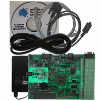
BOARD DEMO DSPICDEM.NET 1
Manufacturer
Microchip Technology
Series
dsPIC™r
Type
Microcontrollerr
Specifications of DM300004-1
Contents
*
Mcu Supported Families
DsPIC30F
Supported Devices
DsPIC30F6014
For Use With
PIC30F5013
Lead Free Status / RoHS Status
Lead free / RoHS Compliant
For Use With/related Products
FCC/JATE PSTN, Ethernet NIC
Lead Free Status / RoHS Status
na, Lead free / RoHS Compliant
Other names
DM300004-1R
DM300004-1R
DM300004-1R


PICDEM.net™ 1 and dsPICDEM.net 2 Connectivity Dev Board User’s Guide
DS51471A-page 90
7.1.12
An Ethernet interface is provided using the Realtek RTL8019 ethernet controller. This
is accessed via the bidirectional bus on PORTD. For detailed operation of this device
please see the RTL8019 data sheet from Realtek
• STATUS LEDs: Four LEDs are provided:
Connection to the Ethernet is supported via the RJ-45 modular connector.
7.1.13
A Microchip 24LC515 serial EEPROM provides 512 Kbit (64 Kbyte) of storage for
constants such as Web pages, linearization tables for sensors and custom data tables.
The 24LC515 is programmable via a two-wire serial I
7.1.14
A Cypress 1 Mbit (64k words) CY7C1021B CMOS Static RAM is provided and can be
used to store temporary data for product development or diagnostic purposes. The
CY7C1021B is accessible via a multiplexed bus on PORTD pins RD0-RD15. The
SRAM control signals, CE, OE and WE are provided by the dsPIC PORTB pins RB9,
RB10 and RB11 respectively.
Two 74HCT573 Octal D-latches are implemented for latching the SRAM address. The
high and low byte control signals, BHE and BLE, of the SRAM are tied to ground,
through zero ohm resistors. Reads and writes to the SRAM are performed in the x16
data mode.
The following is a typical sequence of steps for accessing the external SRAM device:
1. Place 16-bit address on PORTD and set pin direction (TRISD) as outputs
2. Assert ALE (RB12) to a logic ‘1’ from a logic ‘0’ to latch address
3. Assert control signal OE (RB10) to a logic ‘0’ for a read or logic ‘1’ for a write
4. For a write, place data on PORTD
5. Assert CE (RB9) to a logic ‘0’ to select SRAM chip
6. If performing a read, read data on PORTD
7. If performing a write, assert control signal WE (RB11) to a logic ‘1’ from a logic ‘0’
8. Assert control signal CE (RB9) to a logic ‘1’ to deselect the SRAM
7.1.15
Headers J10-J13 provide for a connection to the MPLAB ICE 4K In-Circuit Emulator.
The emulation headers also support the processor adaptor boards (see Section
7.1.21 “Sample Devices”). The processor adaptor boards enable quick change out of
the 80-pin TQFP device.
- LINK STATUS – This LED can be used for link status.
- XMIT and RX – When the board is connected correctly, these are normally lit,
- BNC – This LED is enabled as default and indicates medium type.
and flash OFF (inverted logic), when the board is transmitting or receiving a
packet (respectively).
Serial EE Memory Device
64k x 16 External SRAM
Emulation Header
10-Base T Ethernet
2
C
TM
2004 Microchip Technology Inc.
interface.
Related parts for DM300004-1
Image
Part Number
Description
Manufacturer
Datasheet
Request
R

Part Number:
Description:
Manufacturer:
Microchip Technology Inc.
Datasheet:
Part Number:
Description:
Manufacturer:
Microchip Technology Inc.
Datasheet:
Part Number:
Description:
Manufacturer:
Microchip Technology Inc.
Datasheet:
Part Number:
Description:
Manufacturer:
Microchip Technology Inc.
Datasheet:
Part Number:
Description:
Manufacturer:
Microchip Technology Inc.
Datasheet:
Part Number:
Description:
Manufacturer:
Microchip Technology Inc.
Datasheet:
Part Number:
Description:
Manufacturer:
Microchip Technology Inc.
Datasheet:
Part Number:
Description:
Manufacturer:
Microchip Technology Inc.
Datasheet: