PMF18WE1 Microchip Technology, PMF18WE1 Datasheet - Page 68
PMF18WE1
Manufacturer Part Number
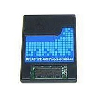
PMF18WE1
Description
PROCESSOR MODULE FOR ICE4000
Manufacturer
Microchip Technology
Datasheet
1.ICE4000.pdf
(98 pages)
Specifications of PMF18WE1
Module/board Type
Processor Module
Product
Microcontroller Modules
Core Processor
PIC18F6585/6680/8585/8680
Lead Free Status / RoHS Status
Contains lead / RoHS non-compliant
For Use With/related Products
ICE4000
Lead Free Status / RoHS Status
Lead free / RoHS Compliant, Contains lead / RoHS non-compliant


MPLAB
8.13
8.14
DS51490A-page 62
SETTINGS DIALOG, VIEW TAB
SETTINGS DIALOG, CLOCK TAB
ICE 4000 User’s Guide
Set viewing properties.
TABLE 8-6:
Set up the emulator clock or select the target board clock. Other options may be
available, depending on device selected and PMF emulator chip.
For more information, see Section 3.6 “Setting Up the Processor Clock”.
8.14.1
TABLE 8-7:
Analyzer
Complex Trigger
(Analyzer) Property
Sheet Always On Top
When Opened
Periodic (Real-Time) Reads
Enabled
Read Period (mS)
Apply To
Other
Emulator
Desired Frequency
Actual Frequency
(and Percent Error)
Dialog
Use Target Board Clock
Optimize for Fast Step
PIC18X Devices (PMFs with PIC18C01/C02)
VIEW TAB
CLOCK TAB –
When the Complex Trigger Settings tab of the MPLAB ICE 4000
Analyzer dialog is open, it will always appear on top of other
MPLAB IDE windows or dialogs when this is checked. If not
checked, the dialog can disappear behind other windows or
dialogs.
Note: The MPLAB ICE 4000 Analyzer dialog must be closed and
then reopened for selections here to take effect.
If checked, real-time memory reads will occur at intervals specified
in the Read Period for registers specified in Apply To.
Specify a the period for memory reads.
Specify if all memory or only memory for those registers displayed
in Watches is read.
Click Show State and Operations Gauge to open an emulator
monitor window (Section 4.10 “Monitoring Emulator States and
Operations”).
The frequency at which you would like emulation to run. Consult
your device data sheet for appropriate frequencies for your device.
The emulator-generated clock frequency and deviation from the
desired frequency.
Use the target board clock, and not the emulator clock, for timing.
Check to speed up stepping. This assumes that you will not
change the frequency while executing/stepping your code,
i.e., frequency checking is suspended.
Note: Do not use with INT RC or Timer 1 Osc.
PIC18X DEVICES (PMFS WITH PIC18C01/C02)
2004 Microchip Technology Inc.
Related parts for PMF18WE1
Image
Part Number
Description
Manufacturer
Datasheet
Request
R

Part Number:
Description:
Manufacturer:
Microchip Technology Inc.
Datasheet:
Part Number:
Description:
Manufacturer:
Microchip Technology Inc.
Datasheet:
Part Number:
Description:
Manufacturer:
Microchip Technology Inc.
Datasheet:
Part Number:
Description:
Manufacturer:
Microchip Technology Inc.
Datasheet:
Part Number:
Description:
Manufacturer:
Microchip Technology Inc.
Datasheet:
Part Number:
Description:
Manufacturer:
Microchip Technology Inc.
Datasheet:
Part Number:
Description:
Manufacturer:
Microchip Technology Inc.
Datasheet:
Part Number:
Description:
Manufacturer:
Microchip Technology Inc.
Datasheet: