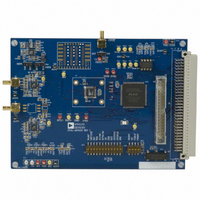
EVAL-AD7655CB Analog Devices Inc, EVAL-AD7655CB Datasheet - Page 7

EVAL-AD7655CB
Manufacturer Part Number
EVAL-AD7655CB
Description
BOARD EVAL FOR AD7655
Manufacturer
Analog Devices Inc
Series
PulSAR®r
Specifications of EVAL-AD7655CB
Number Of Adc's
1
Number Of Bits
16
Sampling Rate (per Second)
1M
Data Interface
Serial, Parallel
Inputs Per Adc
4 Single Ended
Input Range
0 ~ 2 V
Power (typ) @ Conditions
120mW @ 1MSPS
Voltage Supply Source
Analog and Digital
Operating Temperature
-40°C ~ 85°C
Utilized Ic / Part
AD7655
Lead Free Status / RoHS Status
Contains lead / RoHS non-compliant
Preliminary Technical Data
1
For AD7621/AD7641 these are set to +2.5V. Note that setting these to +5V will permanently destruct the ADC.
Table 3. Jumper Description
Table 4. S16 - Configuration Select Switch Description
Note: (OFF = LOW, ON = HIGH)
Table 5. S35 - Configuration Select Switch Description
Note: (OFF = LOW, ON = HIGH)
Jumper
JP1, JP2
JP3
JP4
JP6
JP7
JP8
JP9
JP19
JP20
JP21
JP22
Position
1
2
3
4
5
6
7
8
9
10
11
12
Name
BUFF
VDRV-
REFS
OVDD
VREF+
VDRV+
DVDD
AVDD
REFB
VIO
CNVST
Name
WARP
IMPULSE
BIP
TEN
A0/M0
BYTE/M1
OB/ 2C
SER/ PAR
EXT/ INT
INVSYNC
INVSCLK
RDC
Default
Position
BUFF
-12V
REF
3.3V
+12V
+12V
VDIG/2.5
+5V/2.5
BUF
3.3V
INT
Default
Position
LOW
LOW
LOW
LOW
LOW
LOW
HIGH
LOW
LOW
LOW
LOW
LOW
1
Function
Buffer amplifier: BUFF = use op amps to buffer analog input. NO BUFF = direct input from J1, J2
(SMB).
Buffer amplifier negative supply: Selection of -12V, -5V or GND when using EVAL-CONTROL-
BRDX or voltages on SJ1 in stand alone mode.
Reference selection: REF = use on board reference output for ADC reference. VDD = use analog
supply (AVDD) for ADC reference.
ADC digital output supply voltage: Selction of 2.5V, 3.3V and VDIG. VDIG = +5V when using
EVAL-CONTROL-BRDX or voltage on SJ2 in stand-alone mode.
Reference circuit positive supply: Selection of +12V, +5V or AVDD when using EVAL-CONTROL-
BRDX or voltages on SJ1 in stand alone mode.
Buffer amplifier positive supply: Selection of +12V, +5V or AVDD when using EVAL-CONTROL-
BRDX or voltages on SJ1 in stand alone mode.
ADC digital supply voltage: Selection of +2.5V or VDIG (+5V) when using EVAL-CONTROL-BRDX
or voltage on SJ2 in stand-alone mode.
ADC analog supply voltage: Selection of +2.5V, +5V or EXT when using EVAL-CONTROL-BRDX
Reference buffer: BUFF = use U2 to buffer or amplify reference source. NO BUFF = use reference
directly into ADC.
Gate array I/O voltage: Selection of 3.3V or OVDD. Note: gate array will be damaged if >3.3V (ie.
when using OVDD = VDIG).
CNVST source: INT = use gate array to generate CNVST . EXT = use external source into J3, SMB
for CNVST .
Function
Conversion mode selection: Used in conjunction with IMPULSE. When HIGH with IMPULSE=
LOW, the fastest (Warp) mode is used for maximum throughput. When LOW and IMPULSE =
LOW, Normal mode is used.
Conversion mode selection: Used in conjunction with WARP. When HIGH with WARP = LOW, a
reduced power mode is used in which the power consumption is proportional to the
throughput rate.
For future use.
For future use.
A0, input Mux selection: Used for AD7654/AD7655 (refer to datasheet).
M0, data output interface selection: Used along with M1 for 18-bit ADCs.
BYTESWAP, used for 8-bit interface mode on 16-bit ADCs: MSByte is swapped with LSByte on 8
data lines.
M1, data output interface selection: Used along with M0 for 18-bit ADCs.
Data output select: LOW = Use 2’s complement output. HIGH = Straight binary output.
Data output interface select: LOW = Parallel interface. HIGH = Serial interface.
Serial clock source select: LOW = Use ADC internal serial clock, SCLK is an output. HIGH= Use
external clock, which is MCLK (40 MHz) and SCLK is an input. Not used in parallel reading mode.
Serial sync (SYNC) active state: LOW = SYNC is active HIGH. HIGH = SYNC is active LOW. Used
only for Master mode (internal SCLK). Not used in parallel reading mode.
Serial clock (SCLK) active edge: LOW = Use SCLK falling edge. HIGH = Use SCLK rising edge.
Active in all serial modes. Not used in parallel reading mode.
Read during convert: LOW = Read data after conversion (BUSY = LOW). HIGH = Read data
during conversions (BUSY = HIGH). Used in both parallel and serial interface modes.
Rev. PrW | Page 7 of 22
EVAL-AD76XXCB


